
Page 1223 - 2006 HARLEY FLSTCI SERVICE MANUAL
P. 1223
d0173x3x
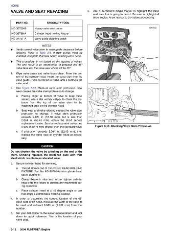
Use a permanent magic marker to highlight the valve seat area that is going to be cut. Be sure to highlight all three angles. Allow marker to dry before proceeding. Figure 3-13. Checking Valve Stem Protrusion
6.
guides must be
SPECIALTY TOOL Neway valve seat cutter Cylinder head holding fixture Valve guide cleaning brush NOTES Verify correct valve stem to valve guide clearance before new If 3-6. Table installed, complete that task before refacing valve seats. This procedure is not based on the lapping of valves. The end result is an interference fit between the 45° valve face and the valve seat which will be 46°. Wipe valve seats and valve faces clean. From the bot- tom of the cylinder head, insert the valve stem into the valve guide. Push on bottom of valve until it contacts the See Figure 3-13. Measure valve stem protrusion. Seat wear causes the valve st
VALVE AND SEAT REFACING
PART NO. HD-35758-B HD-39786-A HD-34751-A refacing. Refer to valve seat. sary. steel which results in accelerated wear. Secure cylinder head for servicing. spark plug hole. ing operation. number. valve seat. 2006 FLSTFSE 2 : Engine
HOME ● ● 1. 2. a. b. c. 3. a. b. c. 4. 5. 3-12