
Page 1218 - 2006 HARLEY FLSTCI SERVICE MANUAL
P. 1218
With the combustion chamber side facing upward,
Checking the opposite diagonal, repeat the proce-
dure to verify that the gasket surface is flat (espe-
Slide a feeler gauge beneath the straightedge to
the cylinder head intersecting the upper and lower
set a straightedge diagonally across the length of
TORQUE 3-7
cially if a head gasket was blown). Discard the head
Check for scratches and nicks on all gasket sealing sur-
if any low spot is 0.006 in. (0.15 mm) or greater.
SPECIALTY TOOL Valve guide cleaning brush Inspect external surfaces, particularly the combustion chamber side, for cracks. Replace the guide if any Lightly hone bore using the VALVE GUIDE HONE Scrub with the VALVE GUIDE CLEANING BRUSH (Part No. HD-34751) to remove any dust or debris. Polish the valve stem with fine emery cloth or steel Carefully measure the inside diameter of the valve Measure the outside diameter of the valve stem Table 3-5. If the clearance between stem and guide exceeds the limits shown, the valve stem Repeat measurements with a new valve to deter- 2006
corners of the gasket surface. check the head for warpage. NOTE For best results, use one of the CYLINDER PLATES (HD-42324-A) in lieu of the straightedge. Lay the upper plate (without vise grip) flat on the machined surface of the head. As a preliminary check, see if the plate rocks from side to side. A head on which the plate rocks is immediately suspect. Insert a feeler gauge between the plate and head at various locations to see if warpage exceeds above specifica- Verify that oil passageways are open and clean. Valve hone guide Prepare valve guides for inspection. (Part No. HD-34723-A). wool to remove carbon buildu
INSPECTION Cylinder Head 1. faces. Check for warpage. 2. a. b. c. tion. 3. Valve Guides PART NO. HD-34723-A HD-34751 1. cracks are found. 2. a. b. c. 3. a. b. to Refer c. d.
6
5
7
11
1
12
2 3
4
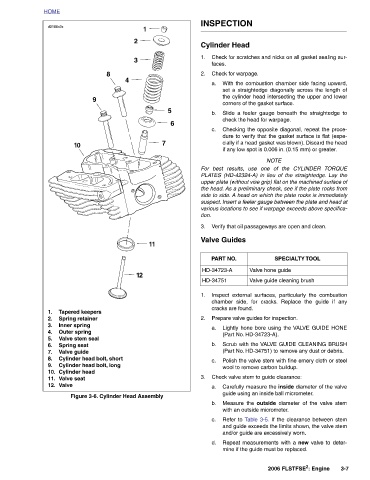
8 Figure 3-6. Cylinder Head Assembly
Tapered keepers Valve stem seal
9 Cylinder head bolt, short Cylinder head bolt, long
10 Spring retainer Inner spring Outer spring Spring seat Valve guide Cylinder head Valve seat
d0166x3x Valve
HOME 1. 2. 3. 4. 5. 6. 7. 8. 9. 10. 11. 12.