
Page 1221 - 2006 HARLEY FLSTCI SERVICE MANUAL
P. 1221
(0.013-0.0025 mm) of finished size. 39964). a. b. bore at top of cylinder head. c. not centrally applied. d. reamer rotates freely. damaged. e. ber side of valve guide. remove any metal shavings or debris. HD-39964). a. b. and valve guide bore. c. d.
NOTE Valve guides must be reamed to within 0.0005-0.0001 in. See Figure 3-10. Obtain the VALVE GUIDE REAMER (Part No. HD-39932), REAMER T-HANDLE (Part No. HD-39847) and REAMER LUBRICANT (Part No. HD- Install T-handle (1) on reamer (2). Apply a liberal amount of reamer lubricant to valve guide bore and bit of reamer. Start bit of reamer into Placing thumb on drive socket of reamer T-handle, apply slight pressure on reamer while rotating in a clockwise direction. Squirt additional lubricant onto reamer and into guide as necessary. CAUTION For best results, do not push on reamer or apply pres- sure to the reamer handle. While excessive pressure res
5. ure. 6. 7. 8.
2
1
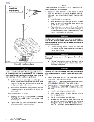
1 2 Figure 3-9. Install Valve Guide CAUTION Always back off ram to allow the valve guide to find cen- ter. Pressing guide into cylinder head in one stroke can bend driver, break guide, distort cylinder head casting and/or damage cylinder head valve guide bore. Verify that support stand (3) and driver (1) are square. Center driver under ram and press valve guide further into bore, but then back off ram again to allow valve guide to find center. Repeat step 3f and then apply pressure to driver until installer sleeve contacts machined area of cyl- Thread 12 mm end of CYLINDER HEAD HOLDIN
Valve guide driver Valve guide installer sleeve Cylinder head stand 3 inder head. Secure cylinder head for service. spark plug hole. 2006 FLSTFSE 2 : Engine
HOME 1. 2. 3. d0169x3x f. g. 4. a. b. 3-10