
Page 861 - 2006 HARLEY FLSTCI SERVICE MANUAL
P. 861
4
5
6
10
1
2 11
3
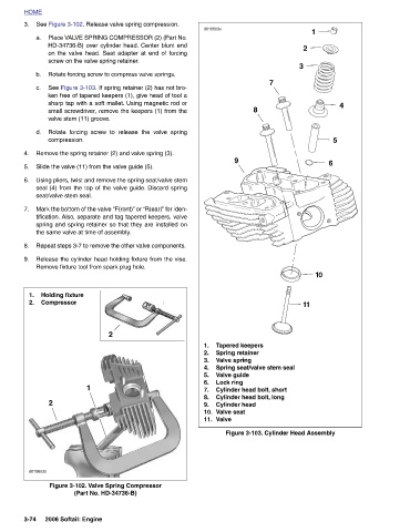
7 Figure 3-103. Cylinder Head Assembly
Tapered keepers
8 Spring seat/valve stem seal Cylinder head bolt, short Cylinder head bolt, long
9 Spring retainer Valve spring Valve guide Lock ring Cylinder head Valve seat
d0166b3x 1. 2. 3. 4. 5. 6. 7. 8. 9. 10. Valve 11.
HD-34736-B) over cylinder head. Center blunt end
Place VALVE SPRING COMPRESSOR (2) (Part No.
on the valve head. Seat adapter at end of forcing
See Figure 3-102. Release valve spring compression.
screw on the valve spring retainer. Rotate forcing screw to compress valve springs. Figure 3-103. If spring retainer (2) has not bro- ken free of tapered keepers (1), give head of tool a sharp tap with a soft mallet. Using magnetic rod or small screwdriver, remove the keepers (1) from the Rotate forcing screw to release the valve spring Remove the spring retainer (2) and valve spring (3). Slide the valve (11) from the valve guide (5). Using pliers, twist and remove the spring seat/valve stem seal (4) from the top of the valve guide. Discard spring Mark the bottom of the valve “F(ront)” or “R(ear)” for iden- tification. Also, separate and t
the same valve at time of assembly. 1
valve stem (11) groove. compression. seat/valve stem seal. Holding fixture Compressor 2006 Softail: Engine
HOME 3. a. b. See c. d. 4. 5. 6. 7. 8. 9. 1. 2. 2 d0156x3x 3-74