
Page 858 - 2006 HARLEY FLSTCI SERVICE MANUAL
P. 858
3-71
3
2006 Softail: Engine
9
6 8
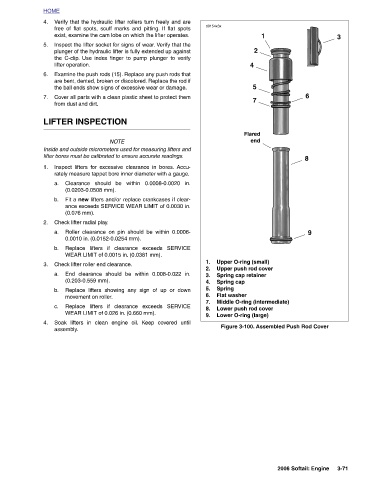
Upper O-ring (small) Upper push rod cover Spring cap retainer Spring cap Flat washer Lower push rod cover Lower O-ring (large)
1 Figure 3-100. Assembled Push Rod Cover
2 5 7 end
4 Flared Middle O-ring (intermediate)
d0154x3x 1. 2. 3. 4. Spring 5. 6. 7. 8. 9.
plunger of the hydraulic lifter is fully extended up against
free of flat spots, scuff marks and pitting. If flat spots
Verify that the hydraulic lifter rollers turn freely and are
Inspect the lifter socket for signs of wear. Verify that the
exist, examine the cam lobe on which the lifter operates.
lifter operation. the C-clip. Use index finger to pump plunger to verify Examine the push rods (15). Replace any push rods that are bent, dented, broken or discolored. Replace the rod if the ball ends show signs of excessive wear or damage. Cover all parts with a clean plastic sheet to protect them from dust and dirt. LIFTER INSPECTION NOTE Inside and outside micrometers used for measuring lifters and lifter bores must be calibrated to ensure accurate readings. Inspect lifters for excessive clearance in bores. Accu- rately measure tappet bore inner diameter with a gauge. Clearance should be within 0.0008-0.0020 in. (0.0203-0.0508 mm).
HOME 4. 5. 6. 7. 1. a. b. 2. a. b. 3. a. b. c. 4.