
Page 974 - 2006 HARLEY FLSTCI SERVICE MANUAL
P. 974
5-9
3
4
2
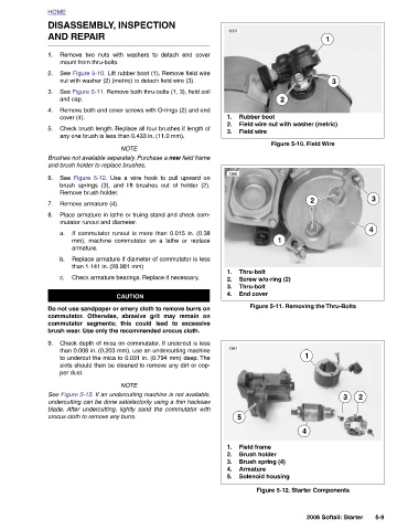
Field wire nut with washer (metric) Figure 5-10. Field Wire Figure 5-11. Removing the Thru-Bolts 1 4 Figure 5-12. Starter Components
3 3 2006 Softail: Starter
1 2
2 1
Rubber boot Field wire Thru-bolt Screw w/o-ring (2) Thru-bolt End cover Field frame Brush holder Brush spring (4) Armature Solenoid housing
6007 1. 2. 3. 7366 1. 2. 3. 4. 7367 5 1. 2. 3. 4. 5.
Remove two nuts with washers to detach end cover
Use a wire hook to pull upward on
Check brush length. Replace all four brushes if length of
See Figure 5-11. Remove both thru-bolts (1, 3), field coil
See Figure 5-10. Lift rubber boot (1). Remove field wire
Remove both end cover screws with O-rings (2) and end
nut with washer (2) (metric) to detach field wire (3).
any one brush is less than 0.433 in. (11.0 mm).
DISASSEMBLY, INSPECTION
NOTE Brushes not available separately. Purchase a new field frame brush springs (3), and lift brushes out of holder (2). Place armature in lathe or truing stand and check com- If commutator runout is more than 0.015 in. (0.38 mm), machine commutator on a lathe or replace Replace armature if diameter of commutator is less than 1.141 in. (28.981 mm) Check armature bearings. Replace if necessary. CAUTION Do not use sandpaper or emery cloth to remove burrs on commutator. Otherwise, abrasive grit may remain on commutator segments; this could lead to excessive brush wear. Use only the recommended crocus cloth. Check d
AND REPAIR mount from thru-bolts. and cap. cover (4). and brush holder to replace brushes. Figure 5-12. See Remove brush holder. Remove armature (4). mutator runout and diameter. armature. per dust. crocus cloth to remove any burrs.
HOME 1. 2. 3. 4. 5. 6. 7. 8. a. b. c. 9.