
Page 71 - GIGABYTE Service Manual-v3.0-110101
P. 71
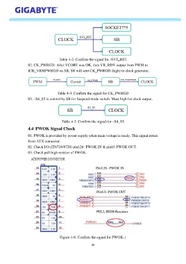
Table 4-2: Confirm the signal for -SYS_RST
                   02. CK_PWRGD: After VCORE was OK, then VR_RDY output from PWM to
                   ICH_VRMPWRGD on SB, SB will sent CK_PWRGD (high) to clock generator.


                                      Table 4-3: Confirm the signal for CK_PWRGD

                   03. –S4_S5 is control by SB for Suspend mode switch. Must high for clock output.


                                         Table 4-3: Confirm the signal for –S4_S5
                   4.4  PWOK Signal Check

                   01. PWOK is provided by power supply when main voltage is ready. This signal enters

                   from ATX connector.
                   02. Check I/O (IT8718/8720) pin126- PWOK IN & pin63-PWOK OUT.
                   03. Check pull high resistor of PWOK.


                                       Figure 4-8: Confirm the signal for PWOK-1

                                                            49