Page 10 - PR 2014 2016 05 Renewable Energies
P. 10

112   Renewable Energies | Progress Report


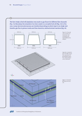
               The first study in fuel cell simulation was made on gas fluxes for different flow channels
               (Fig. 11), Nowadays the simulation has been made in a complete fuel cell (Fig. 12). In this
               case, many chemical phenomena are involved depending on which layer is on study, heat
               transfer, gas flux in porous media and flow channels, electrochemical reactions (Fig. 13).

                          0.8 mm               0.8 mm                  0.8 mm               Figure 11. Channel
                                                                                            cross sections and
                                                                                            dimensions: (a)
                                                                                            rectangular, (b)
                                                                                            trapezoidal and (c)
               0.8 mm                                                                       stepped.

                                                                                    0.4 mm

                           MEA                  MEA                     MEA
                          0.8 mm               1.05 mm                1.05 mm


                                                                                            Figure12. A complete
                                                                                            fuel cell with two gas
                                                                                            flow channels, two
                                                                                            gas diffusion layers,
                                                                                            two catalytic layers
                                                                                            and a membrane.


                                                                                            Figure 13. Detail of
                                                                                            the layers of a fuel
                                                                         Catalyst           cell.
                                           O2 Channels                Layers (CLs)
                             Cathode


                 Membrane      Anode


                                            H2 Channels              Gas Diffusion
                                                                     Layers (GDLs)
                   z
                 y    x


                         Instituto de Pesquisas Energéticas e Nucleares
   5   6   7   8   9   10   11   12   13   14   15