
Page 103 - Handout of Computer Architecture (1)..
P. 103
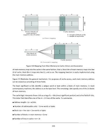
Figure 4.8 Mapping from Main Memory to Cache: Direct and Associative

               of main memory map into the cache in the same fashion; that is, block Bm of main memory maps into line
               L0 of cache, block Bm+1 maps into line L1, and so on. The mapping function is easily implemented using
               the main memory address.


               Figure 4.9 illustrates the general mechanism. For purposes of cache access, each main memory address
               can be viewed as consisting of three fields.


               The  least  significant  w  bits  identify  a  unique  word  or  byte  within  a  block  of  main  memory;  in  most
               contemporary machines, the address is at the byte level. The remaining s bits specify one of the 2s blocks
               of main memory.

               The cache logic interprets these s bits as a tag of s- r bits (most significant portion) and a line field of r bits.
               This latter field identifies one of the m = 2r lines of the cache. To summarize,

               ■ Address length = (s + w) bits

                ■ Number of addressable units = 2s+w words or bytes

               ■ Block size = line size = 2w words or bytes

               ■ Number of blocks in main memory = 2s+w

               ■ Number of lines in cache = m = 2r


                                                             103