
Page 20 - Handout of Computer Architecture (1)..
P. 20
designating one of the words in memory (numbered from 0 to 999). The control unit operates
the IAS by fetching instructions from memory and executing them one at a time. We explain
these operations with reference to Figure 1.6. This figure reveals that both the control unit and
the ALU contain storage locations, called registers, defined as follows:
■ Memory buffer register (MBR): Contains a word to be stored in memory or sent to the I/O unit,
or is used to receive a word from memory or from the I/O unit.
■ Memory address register (MAR): Specifies the address in memory of the word to be written
from or read into the MBR.
■ Instruction registers (IR): Contains the 8-bit opcode instruction being executed.
■ Instruction buffer register (IBR): Employed to hold temporarily the right- hand instruction from
a word in memory.
■ Program counter (PC): Contains the address of the next instruction pair to be fetched from
memory.
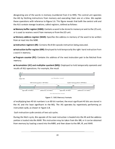
■ Accumulator (AC) and multiplier quotient (MQ): Employed to hold temporarily operands and
results of ALU operations. For example, the result
Figure 1.7:IAS Memory Formats
of multiplying two 40-bit numbers is an 80-bit number; the most significant 40 bits are stored in
the AC and the least significant in the MQ. The IAS operates by repetitively performing an
instruction cycle, as shown in Figure 1.8.
Each instruction cycle consists of two sub cycles.
During the fetch cycle, the opcode of the next instruction is loaded into the IR and the address
portion is loaded into the MAR. This instruction may be taken from the IBR, or it can be obtained
from memory by loading a word into the MBR, and then down to the IBR, IR, and MAR.
20