
Page 17 - rise 2017
P. 17
Method 2: Power Factor Correction (PFC) by Using Bridgeless Topology
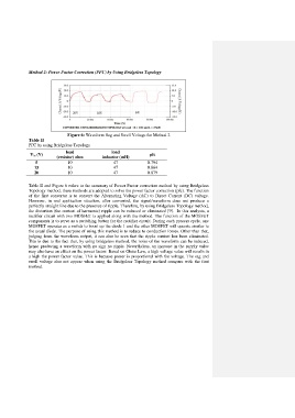
Figure 6: Waveform Sag and Swell Voltage for Method 2
Table II
PFC by using Bridgeless Topology
load load
V in (V) pfc
(resistor) ohm inductor (mH)
5 10 47 0.794
15 10 47 0.864
20 10 47 0.879
Table II and Figure 6 refers to the summary of Power Factor correction method by using Bridgeless
Topology method, these methods are adopted to solve the power factor correction (pfc). The function
of the first converter is to convert the Alternating Voltage (AC) to Direct Current (DC) voltage.
However, in real application situation, after converted, the signal/waveform does not produce a
perfectly straight line due to the presence of ripple. Therefore, by using Bridgeless Topology method,
the distortion (the content of harmonic) ripple can be reduced or eliminated [9]. In this analysis, a
rectifier circuit with two MOSFET is applied along with the method. The function of the MOSFET
components is to serve as a switching button for the rectifier circuit. During each process cycle, one
MOSFET operates as a switch to boost up the diode 1 and the other MOSFET will operate similar to
the usual diode. The purpose of using this method is to reduce to conduction losses. Other than that,
judging from the waveform output, it can also be seen that the ripple content has been eliminated.
This is due to the fact that, by using bridgeless method, the noise of the waveform can be reduced,
hence producing a waveform with no sign no ripple. Nevertheless, an increase in the supply value
may also have an effect on the power factor. Based on Ohms Law, a high voltage value will results in
a high the power factor value. This is because power is proportional with the voltage. The sag and
swell voltage also not appear when using the Bridgeless Topology method compare with the first
method.