
Page 18 - rise 2017
P. 18
Method 3: Power Factor Correction (PFC) by Using Bridgeless Topology and Interleaved
Converter
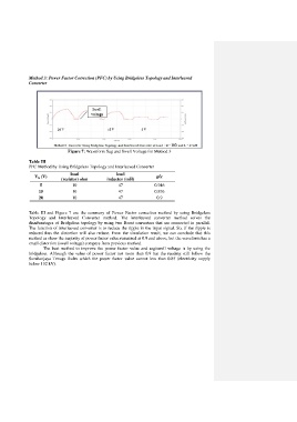
Figure 7: Waveform Sag and Swell Voltage for Method 3
Table III
PFC Method by Using Bridgeless Topology and Interleaved Converter
load load
V in (V) pfc
(resistor) ohm inductor (mH)
5 10 47 0.946
15 10 47 0.876
20 10 47 0.9
Table III and Figure 7 are the summary of Power Factor correction method by using Bridgeless
Topology and Interleaved Converter method. The interleaved converter method solves the
disadvantages of Bridgeless topology by using two Boost converters that are connected in parallel.
The function of interleaved converter is to reduce the ripple in the input signal. So, if the ripple is
reduced thus the distortion will also reduce. From the simulation result, we can conclude that this
method as show the majority of power factor value remained at 0.9 and above, but the waveform has a
small distortion (swell voltage) compare from previous method.
The best method to improve the power factor value and sag/swell voltage is by using the
bridgeless. Although the value of power factor not more than 0.9 but the reading still follow the
Suruhanjaya Tenaga Rules which the power factor value cannot less than 0.85 (electricity supply
below 132 kV).