
Page 55 - UL_Report On_Part 1
P. 55
45 IITGN-UL/Façade 46 IITGN-UL/Façade
2 1 # R 5 7 2 1 # R 6 5
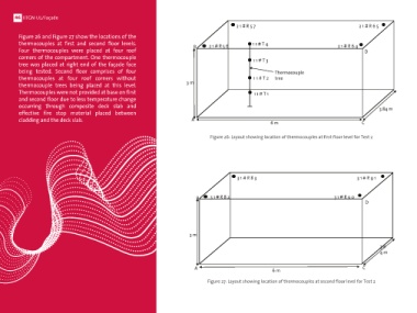
(ii) Test 2: Standard glass + ACP assembly Figure 26 and Figure 27 show the locations of the
This test was performed with standard glass and ACP assembly being mounted on one thermocouples at first and second floor levels. B 2 1 # R 5 6 1 1 # T 4 2 1 # R 6 4
face of the facility over the full height. The test aimed at assessing the performance of Four thermocouples were placed at four roof D
standard toughened glass over locally available glass in Indian markets. Saint Gobain corners of the compartment. One thermocouple 1 1 # T 3
toughened glass of 1200 x 400 mm size and 4 mm thickness was used. 60% Glass and tree was placed at right end of the façade face
40% ACP was used in comprising the whole assembly (same as in Test 1). The test was being tested. Second floor comprises of four Thermocouple
subjected with ignition source placed within the compartment unlike Test 1. All other thermocouples at four roof corners without 1 1 # T 2 tree
specifications related to cladding framework, fire stop and construction details were thermocouple trees being placed at this level. 3 m
similar to Test 1. Thermocouples were not provided at base on first 1 1 # T 1
(a) Instrumentation and second floor due to less temperature change
This test was instrumented at all three levels with K-type thermocouples (TC), strain occurring through composite deck slab and 3.84 m
gauges, video and thermal imaging cameras. Specifications of these instrumentation effective fire stop material placed between
were similar to that in Test 1. cladding and the deck slab. A 6 m C
Ground floor level was instrumented with 9 thermocouples and one thermocouple tree
placed at the center of the compartment to measure the temperature profile across the Figure 26: Layout showing location of thermocouples at first floor level for Test 2
height. Figure 25 shows the locations of the thermocouples within the compartment
along with thermocouple tree. ABCD represents the façade face being tested of
compartment 1 at ground floor level. Nomenclature for thermocouples is similar to that
employed in Test 1. Eight thermocouples were placed at eight corners of the room
whereas TC 13 was placed in middle of the compartment at base level.
3 1 # R 8 3 3 1 # R 9 1
1 1 # R 2 3 1 1 # R 3 1
1 1 # T 4 B 3 1 # R 8 2 3 1 # R 9 0 D
B 1 1 # R 2 2 1 1 # R 3 0
1 1 # T 3 D
Thermocouple
1 1 # T 2 tree 3 m
3 m
1 1 # T 1 3.8
1 1 # B 2 4 m
1 1 # B 10
1 1 # B 1 3
3.84 m A 6 m C
1 1 # B 1 1 1 # B 9
A C Figure 27: Layout showing location of thermocouples at second floor level for Test 2
6 m
Figure 25: Layout showing location of thermocouples at ground floor level for Test 2