
Page 88 - UL_Report On_Part 1
P. 88
79 IITGN-UL/Façade 80 IITGN-UL/Façade
(iv) Test 4: Standard glass – Internal fire spread
This test was performed to study the behavior of internal fire
spread with glass as façade material. The aim was to study the
performance of normal fire stop material provided in form of
plywood planks between façade framework and slab. Thus, the test
face of the compartment was provided with one row of Saint
Gobain toughened glass of 1200 x 400mm size with 6 mm 1 3 # R 7 9 1 3 # T 1 1 3 # R 3 3
thickness attached to aluminium framework fixed between
concrete beam and masonry wall at either ends. The same 1 3 # R 2 9
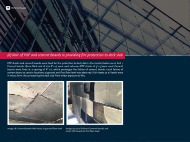
(d) Role of POP and cement boards in providing fire protection to deck slab arrangement was replicated at all three levels. A gap of about B 1 3 # R 7 3 1 3 # R 3 2 1 3 # T 2 1 3 # R 6 8
150mm between the deck slab and masonry at all levels was filled D
with plywood planks as stopping material.
POP sheets and cement boards were fixed for fire protection to deck slab in the similar fashion as in Test 1. 1 3 # T 3
Cement boards 18mm thick and of size 8’ x 4’ were used, whereas POP sheets of 3’ x 3’were used. Cement (a) Instrumentation 1 3 # 9 3
boards were fixed at a spacing of 8’’ c/c, which prolonged the failure of cement boards. Local failure of Thermocouple
cement board at certain locations at ground and first floor level was observed. POP sheets at all levels were The test compartment was instrumented with K-type 3 m 1 3 # T 4 tree
in intact form thus protecting the deck slab from direct exposure to fire.
thermocouples (TC), strain gauges, video and thermal imaging 1 3 # B 7
cameras. Specifications of instrumentation used were similar to 1 3 # B 1 2
that used for Test 1. 3 m
Ground floor level was instrumented with 12 thermocouples and
one thermocouple tree located at center of masonry partition wall. 1 3 # B 1 1 1 3 # B 9 7 1 3 # R 7 8
One of the 12 thermocouples was placed beneath cement board at A 6 m C
middle beam base to observe the effectiveness of cement board. Figure 33: Layout showing location of thermocouples at ground floor level for Test 4
Another TC was placed at mid height of partition wall where out of
plane displacement of masonry wall was attempted to measure
using LVDT. Figure 33 shows the location of the thermocouples at
ground floor level within the compartment along with
thermocouple tree.
Image 28: Cement boards held intact at ground floor level Image 29: Local failure of cement boards and
intact POP boards at first floor level