
Page 190 - Womens Pavilion
P. 190
“Oil-Less” Scroll Medical Air
3.0 System Operation
3.2 Initial Start-up Check all voltages supplied to the LifeLine® system
to ensure they are the required value and phases
CAUTION: Complete the prestart-up procedure needed by the control panel.
before continuing with the initial start-up
procedure Open the inlet isolation valve on each compressor.
Open the outlet isolation valve on each compressor.
WARNING:
To prevent electrical shock, ensure that Open the receiver isolation valves.
ALL electrical power to the system is OFF,
including the disconnect switches and Close the receiver bypass valve.
Automatic-Manual-Off touch screens on
the control panel. The facility’s supply Close the DP/CO sensor isolation valve.
circuit breaker should also be locked out.
Close the inlet and outlet valves on both dryer/
fi lter/regulator assemblies.
NOTE: DO NOT ADD OIL TO THE COMPRESSOR.
The design of the LifeLine® Scroll compressor Close the outlet isolation valve.
is totally oil-less. It is not necessary to fi ll the
crankcases with oil. Apply power to the system and turn the disconnect
switches to “On”.
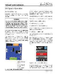
Inside the control panel, make sure that all unit
printed circuit boards are set to the manual Inside the control cabinet, switch one of the unit
override “Off ” position. This is indicated by the printed circuit boards from the manual override
middle position “X” on the three-position sliding “Off ” position to the bottom position, the default
switch as shown in Figure 3.2. “Automatic” mode. Make sure the Pump Mode on
the Unit touchscreens are in the Off position, see
Figure 3.3.
Manual Override
Switch Figure 3.3 Unit Screen - Off Position
O - On Manual Check for correct direction of rotation of each
X - Off compressor by pressing the “Rotation” button
A - Automatic on touchscreen display (found in the Service
Figure 3.2 Unit PCB Override Switch
3-3 4107 9000 69.06