
Page 527 - Womens Pavilion
P. 527
TotalAlert Infinity™ NFPA Medical Gas Notification System
5.3.4 Install New Components
1. Mount the I/O Modules to the large
adapter bracket using the nuts provided.
NOTE: I/O Modules and Power Supply will
need to be daisy chain connected via the
grey cables supplied with each I/O module
(See figure 214).
2. Connect the grey cable(s) provided; from
the power supply to the white sockets on
the I/O modules in a daisy chain manner.
3. The last module in the chain needs to
have the #1 DIP switch set to “ON” (See
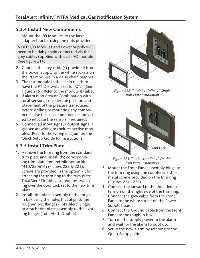
Figure 215). Refer to the module ID label. Figure 222: TotalAlert Infinity™ Single
4. If alarm is an Area or Combination with Trim Plate Installation
local sensors, consider the position and
placement of the pressure transducers
before drilling or mounting any compo-
nents. Use the sensor adapter kits provid-
ed to relocate the sensors if required.
5. Connect all input signal / output signal /
gas sensor wiring to their respective mod-
ules. Refer to the wiring diagram on the
Quick Setup Guide for instructions.
5.3.5 Install Trim Plate Door Lock
1. Remove the trim ring from the standard
trim plate and install the correspond- Figure 223: TotalAlert Infinity™ Double
ing trim plate from retrofit option kit Trim Plate Installation
(4107220616) (Figures 222 & 223). 3. Mount the Front Panel assembly hinge to
Screws are provided in the option kit for the trim ring using the countersink sheet
attaching the trim ring to the trim plate. metal screws provided on the trim ring
TotalAlert Double also requires switch- (Figures 224 - 226).
1
ing over the door lock set to the new trim 4. Connect the lanyard to the threaded ex-
plate. tension on the right side of the trim ring.
2. Install trim plate assembly to the rough- 5. Connect the grey cable from the Front
in box using the holes that align to the Panel to the white socket on the Power
rough-in box flanges (TotalAlert Single), Supply board.
1
or attach trim plate assembly to the exist- 6. Connect the Ground cable from the Front
ing hinges (TotalAlert Double). Panel to the rough-in box.
1
7. Turn on the supply power to the alarm
and wait for the alarm to boot up.
8. Setup the new alarm by referring to the
Quick Setup guide.
4107 9016 58.02 5-8