Page 524 - Womens Pavilion
P. 524

TotalAlert Infinity™ NFPA Medical Gas Notification System


                                                                 5.3 Retrofit of TotalAlert Alarm
                                                                                                 1
                 Trim Plate
                                                                 Panels

            Trim Ring                                            5.3.1 Remove Components from Ex-
                                                                 isting Alarm

                                                                 1.  Open old alarm panel to be retrofitted
                                                                    and ensure that the retrofit kit to be in-
                                                                    stalled is correct according to the number
                                                                    of Signal Inputs, Relay outputs, and/or
                                                                    Gas Sensor signals (See Appendix A).
                                                                 2.  Ensure that you have the additional trim
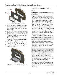
                    Figure 216: Retrofit Area Trim Panel
                                                                    kit for retrofitting a TotalAlert1 Single or
            1.  Mount the Front Panel assembly to the               Double alarm panel (4107220616).
               trim ring using the countersink sheet             3.  Test Master alarm signals to validate wir-
               metal screws provided on the trim ring               ing and document all signal wires coming
               (Figure 217).                                        into the box with alarm type and loca-
            2.  Connect the lanyard to the threaded ex-             tions prior to disconnecting the front
               tension on the right side of the trim ring.          panel.  This information will be required
            3.  Connect the grey cable from the Front               to setup the new alarm.
               Panel to the other white socket on the            4.  Turn off the supply power to the alarm.
               Power Supply board.
            4.  Connect the ground cable from the Front           CAUTION: Verify that power has been
               Panel to the rough-in box using the pro-           turned off prior to working on the alarm.
               vided self-drilling screw.                        5.  Remove and discard the front panel
            5.  Turn on the supply power to the alarm               from the existing alarm. For TotalAlert1
               and wait for the alarm to boot up.                   Double, remove the door from the hinges,
            6.  Setup the new alarm by referring to the             remove the lock set and set aside, and
               Quick Setup guide.                                   discard the door.


                                                                  NOTE: For TotalAlert1 alarms, all internal
                                                                  components will need to be removed and
                                                                  replaced with new components.

                                                                 6.  Remove and discard of all the compo-
                                                                    nents from the alarm rough-in box.
                                                                 7.  Ensure that no low voltage signal wiring
                                                                    is pulled through the input power knock-
                                                                    outs inside of the rough-in box.
                                                                 8.  Mount new power supply adapter
                                                                    bracket (small bracket included with kit
                                                                    4107220616) reusing the hardware and
                Figure 217: Front Panel Assembly Mounting
                                                                    location from the old power supply (Fig-
                                                                    ure 218).


                                                             5-5                                4107 9016 58.02
   519   520   521   522   523   524   525   526   527   528   529