
Page 526 - Womens Pavilion
P. 526
TotalAlert Infinity™ NFPA Medical Gas Notification System
CAUTION: Ensure that the pressure on the 5.3.3 Install New Power Supply
pipeline in the alarm area has been released 1. Mount the new Power Supply (B05) to the
before removing any components from the adapter bracket using the nuts provided
pipeline connection. (Figures 218 - 221).
2. Locate the Ground cable attached to the
3. Remove any existing fittings or adapters
from the gas tube. power supply and connect the ring ter-
4. Install the gas specific DISS demand check minal end to the rough-in box for chassis
valve from the supplied tubing package ground. Use the self-drilling screw pro-
into the appropriate tube. To prevent vided.
gas leaks, wrap Teflon tape a minimum 3. Remove the 4 corner screws from the
of three times around the fitting pipe Power Supply cover and remove the cover.
threads. 4. Connect the supply power Line and Neu-
5. Tighten the adapter until you feel resis- tral wires to the terminal block.
tance; then turn the fitting 2 full turns. 5. Connect the supply power Ground wire
to the rough-in box.
NOTE: If the DISS demand check thread size 6. Replace the power supply cover and
is not compatible with the existing tubing screws.
connection; use the included fitting kits to
adapt as needed. Fitting/adapter kit needs
to be installed upstream from the DISS con-
nection at the gas sensor.
6. Install the gas specific transducer.
7. Tighten the DISS nut until you feel resis-
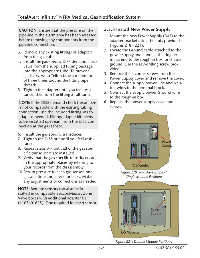
tance. Power
Supply
8. Repeat steps 3-7 until all of the gas spe-
cific transducers are installed.
9. Verify that the gas specific transducers are
in the appropriate places by referring to
your records from the disassembly. I/O Modules
10. Return pressure to each gas sensor, one Figure 220: TotalAlert Infinity™
gas at a time and check for leaks. Make Single Module Positions
any adjustments or corrections as needed.
NOTE: Remote sensors can also be in-
stalled in compatible BeaconMedæs Zone
Valve boxes with additional adapter kit
(4107401625). One required for each sensor.
Power
Supply
I/O Modules
Figure 221: Double Module Positions
5-7 4107 9016 58.02