
Page 525 - Womens Pavilion
P. 525
TotalAlert Infinity™ NFPA Medical Gas Notification System
CAUTION: Ensure that the pressure on the
pipeline in the alarm area has been released
Power before removing any components from the
Supply pipeline connection.
2. Remove any existing fittings or adapters
from the gas tube in the rough-in box.
3. Install the gas specific DISS demand check
valve from the supplied tubing package
into the appropriate gas tube. To prevent
gas leaks, wrap Teflon tape a minimum
I/O
Modules of three times around the fitting pipe
threads.
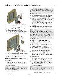
Figure 218: TotalAlert Infinity™ Adapter Bracket 4. Tighten the adapter until you feel resis-
Mounting Single tance; then turn the fitting 2 full turns.
9. Snap the I/O module adapter brack-
et (large bracket included with kit NOTE: If the gas transducer needs to be
4107220616) onto the standoffs at the repositioned in the rough-in box or thread
rear of the rough-in box (Figure 219). size / fitting style is not compatible; use the
included fitting kits to adapt or relocate as
needed. Fitting/adapter kit needs to be in-
Power stalled upstream from the DISS connection
Supply
at the gas sensor.
5. Install the gas specific transducer.
6. Tighten the DISS nut until you feel resis-
tance.
7. Repeat steps 2-6 until all of the gas spe-
cific transducers are installed.
8. Verify that the gas specific transducers are
in the appropriate places by referring to
I/O your records from the disassembly.
Modules 9. Return pressure to each gas sensor, one
gas at a time and check for leaks. Make
Figure 219: TotalAlert Infinity™ Double Adaptor
Bracket Mounting any adjustments or corrections as needed.
5.3.2 Install Gas-Specific Sensors Remote Sensors
(Area or Combination alarms only) 1. Sensors are packaged loose so they can
easily be installed remotely.
Local Sensors 2. Remote sensors are installed directly to
1. Install the TotalAlert Infinity™ gas specific the pipeline outside of the rough-in box.
transducers following your records from Pipeline connections are to be made to
the disassembly. the top of the pipe.
NOTE: If a DISS demand check valve is not NOTE: If a DISS demand check valve is not
in place then one will need to be installed in place then one will need to be installed
to comply with NFPA 99. to comply with NFPA 99.
Figure 221: Double Module Positions
4107 9016 58.02 5-6