
Page 521 - Womens Pavilion
P. 521
TotalAlert Infinity™ NFPA Medical Gas Notification System
5.1.2 Install New Components
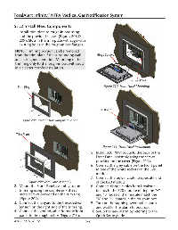
1. Install trim plate to rough-in box using
4 of the provided screws (Figures 208 &
209). Slots in the trim plate will align with
existing holes in the rough-in box flanges.
NOTE: Trim ring portion can be removed
from the trim plate if the surrounding wall Hinge Screws
area is in good condition. Mounting of the
trim ring only to the rough-in box will result
in a cleaner retrofit installation.
Lanyard Nut
Trim Ring Figure 210: Front Panel Mounting
B20 Board
Figure 208: Retrofit Trim Ring Installation
Trim Plate
Figure 211: Front Panel Installation
5. Install B20 I/O module to the back of the
Front Panel assembly using the screws
provided on the cover (Figure 211).
6. Connect the grey cable on the Front panel
to one of the white sockets on the B20
module.
7. Connect the power cable to opposite end
Figure 209: Trim Plate Assembly of the B20 module.
2. Mount the Front Panel assembly to the 8. Connect ribbon cables from breakout
trim ring using the countersink sheet boards to the B20 module noting the “A”
metal screws provided on the trim ring and “B” sides of the module match the
(Figure 209). “A” and “B” boards in the rough-in box.
3. Connect the lanyard to the threaded ex- 9. Turn on the supply power to the alarm
tension on the right side of the trim ring. and wait for the alarm to boot up.
4. Connect the ground cable from the front 10. Setup the new alarm by referring to the
panel to the rough-in box (Figure 210). Quick Setup guide.
4107 9016 58.02 5-2