Page 4 - Router Boss Manual
P. 4

A                 M


                                               Q       P
                              L                                            K       C
                                                                     J
                                        I

                                                                                             E
                    R        H                                          B              D                N

                                               F                                             O

                              G


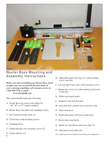
        Router Boss Mounting and

        Assembly Instructions
                                                               H - Adjustable guide rail wings (4) with mounting
                                                                   screws and pins
        Before you start assembling your Router Boss, check
        to make sure you received all the parts listed. If     I - Left and right front scales with mounting screws
        you’re missing something, call customer service at
        1-866-966-3728 or email                                J - Sliding bar cursors (2) with mounting knobs and
                                                                   T-slot nuts
               service@chipsfly.com

                                                               K - White storyboard inserts
        The carton should contain the following:
                                                               L - Magnetic front side dust port
        A - Router Boss box beam with sliding bar
            (36”, 42” or 47” length) installed                 M - Rear dust port vacuum hose extension wand

        B - Router Boss base plate with mounting screws        N - Allen wrench set


        C - Box beam mounting cleats (2)                       O - Router base plate with laser center point

        D - Fixed fence with mounting screws                   P - Router plate stop blocks

        E - Clamping block
                                                               Q - Knobs for stop blocks and router plate (3)
        F - Guide rail rules with mounting screws (2)
                                                               R - Aluminum fixed guide rails
        G - Guide rail base (2)                                (For complete parts list and exploded view drawing, turn to Appendix 1.)
        4
   1   2   3   4   5   6   7   8   9