
Page 8 - Router Boss Manual
P. 8
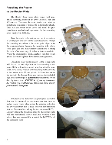
Attaching the Router

        to the Router Plate


             The  Router  Boss  router  plate  comes  with  pre-
        drilled mounting holes for the DeWalt model 625 and
        621 routers.  To mount the router to the plate, start by
        installing a centering or pointed bit in the router chuck.
        Then turn the router upside down and install the pro-
        vided 6mm washer-head cap screws in the mounting
        holes snugly, but not tight.


             Turn the router right-side up and set it on a piece
        of white paper and turn on the laser cross hairs. Plunge
        the centering bit and see if the center point aligns with
        the laser cross hairs. Because the mounting holes allow
        some play, you can make minor adjustments to bring
        the point of the centering bit in line with the crosshairs.
        When the alignment is good, carefully turn the router
        upside down and tighten down the mounting screws.

              Attaching other model routers to the router plate
        will depend on the alignment of the mounting screw
        holes. If the hole pattern won’t interfere with the laser
        and LED circuits, you can drill mounting holes directly
        in the router plate. If you plan to dedicate the router
        for use with the Router Boss, you can use the included
        high-bond tape strips to permanently mount the router
        directly to the plate. CAUTION: If you try to remove
        the router, you could damage the router plate and/or
        your router’s base plate.


             We also have a transition (adapter) plate available
        that  can be custom-fit to your router and that then at-
        taches to our router plate using the existing holes for
        the DeWalt router. You’ll need to notch the transition
        plate to fit around the wiring for the lasers and LEDs.
        Loosely attach the transition plate to the router plate
        with the washerhead screws, mark the location of the
        wires, then use a round file to notch the BOTTOM of
        the transition plate.


        8