
Page 6 - Router Boss Manual
P. 6
small legs on the piece with the cam handle fit into a
groove on the back of the padded block). With the black
release button pushed in, you should be able to easily
slide the clamp block along the sliding bar. Releasing
the button allows the clamp to engage the toothed ribs
on the face of the slot. A pair of spring plungers remove
play by pushing the sliding jaws away from the slid-
ing bar. You
can use a fine
screwdriver to
adjust the ten-
Assembling the Router Boss sion - clock-
wise for more
With the box beam mounted, begin assembly by tension, coun-
attaching the Router Boss base plate to the box beam, terclockwise
using the 1/4” flathead ma- for less).
chine screws in the coun-
tersunk holes first and then Next install the front scales on the face of the ma-
the 1/4” caphead machine chine. Note that the scales read right to left. The 0 to
screws in the holes near the 12” scale mounts on the left side of the machine and
rear edge. Then attach the the 12” to 24” scale mounts on the right. Using two
guide rail rules along either #4 flat head screws, mount each scale so that it extends
side of the base plate. Align about 4” out from each end of the box beam. (On 360
the zero mark with the front machine do not extend right scale.)
edge of the box beam.
Install the knobs and T-track nuts on the sliding
Next install the fixed fence to the sliding bar. But bar cursors. Then slide the nuts into the T-slots on the
first, cover the clamping face of the fence with the pro- sliding bar and snug up the knobs to hold the cursors in
vided self-stick textured rubber pad to help keep work- place.
pieces from slipping. Trim any excess from the edges
so it clears the box beam when you use the sliding bar Use the
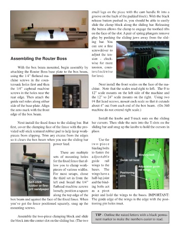
power feed. two-piece
binding bolts
There are multiple to fasten the
sets of mounting holes adjustable Binding bolt
for the fixed fence that al- guide rail Guide rail base
low you to clamp work- wings to the Adjustable guide
pieces of various widths. bases. The rail wings
For most setups, chose wings have a Positioning
the third set in from the half-lap joint pins
Self-stick left end. Install the 1/4” and the bind-
rubber or fine- flathead machine screws ing bolts act
grit sandpaper loosely, position a square as a pivot
along the top edge of the point and hold the wings to the bases. IMPORTANT:
box beam and against the face of the fixed fence. When The guide edge of the wings is the edge with the posi-
you’ve got the fence positioned squarely, snug up the tioning pin holes inset.
mounting screws.
Assemble the two-piece clamping block and slide TIP - Outline the raised letters with a black perma-
the block into the center slot on the sliding bar. (The two nent marker to make the numbers easier to read.
6