
Page 7 - Router Boss Manual
P. 7
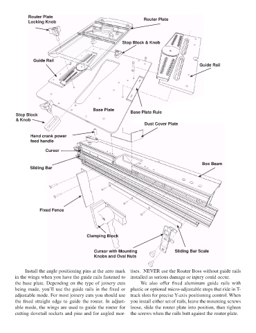
Router Plate                                           Router Plate
               Locking Knob


                                                           Stop Block & Knob


                 Guide Rail
                                                                                                Guide Rail


                                              Base Plate
         Stop Block                                            Base Plate Rule
         & Knob
                                                                      Dust Cover Plate


                Hand crank power
                feed handle

                       Cursor


                                                                                                  Box Beam
               Sliding Bar


                    Fixed Fence


                                           Clamping Block


                                              Cursor with Mounting                   Sliding Bar Scale
                                              Knobs and Oval Nuts


             Install the angle positioning pins at the zero mark  tises.  NEVER use the Router Boss without guide rails
        in the wings when you have the guide rails fastened to  installed as serious damage or injury could occur.
        the base plate. Depending on the type of joinery cuts       We  also  offer  fixed  aluminum  guide  rails  with
        being made, you’ll use the guide rails in the fixed or  plastic or optional micro-adjustable stops that ride in T-
        adjustable mode. For most joinery cuts you should use  track slots for precise Y-axis positioning control. When
        the fixed straight edge to guide the router. In adjust-  you install either set of rails, leave the mounting screws
        able mode, the wings are used to guide the router for  loose, slide the router plate into position, then tighten
        cutting dovetail sockets and pins and for angled mor-  the screws when the rails butt against the router plate.
                                                                                                                   7