
Page 5 - Router Boss Manual
P. 5
Mounting the Router Boss
Before you assemble your Router Boss, we sug-
gest that you first mount the box beam assembly. Most
users mount it on a wall, but you can also mount it on
a high bench or other support. You’ll want to choose a
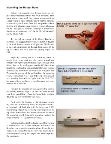
location for your Router Boss that has good overhead Mark a level line on the wall at a good working
lighting and adequate open space to provide clearance height (~ 48” above floor)
for the sliding rail to travel its full range in either direc-
tion (from approximately 64” for the Model 360 to 86”
for the Model 470).
To take full advantage of the Router Boss’s ca-
pabilities, we suggest that you NOT mount it directly
to the wall. Instead, mount a 36” piece of 2X8 lumber
to the wall, then mount the Router Boss on it with the
top face of the box beam flush with the top edge of the
2X8.
Begin by cutting the 2X8 mounting board to
length, then rip or joint one edge so it’s smooth and
straight with square (not rounded) edges. Using a level,
draw a line on the wall approximately 48” above floor
level (or a comfortable working height for you). Locate Drive 5/16” lag screws into wall studs or use
and mark the position of the wall studs along the line. heavy-duty wall anchors to mount board
Transfer the spacing of the wall studs to the mounting
board, counterbore two 1”-dia. holes 1/2” deep at each
stud marking, then drill 5/16” pilot holes for 5/16” X 4”
lag screws. Slip a washer over each lag screw and insert
them in the pilot holes.
Position the mounting board against the wall so Counterbore recess for washer and
the freshly trimmed edge is on top and lined up with lag screw heads
your level pencil line. Once the board is in position,
drive the lag screws into the wall studs.
Next, mark the location of the aluminum mount-
ing cleats on the mounting board, placing them about 4”
in from each end. Drill pilot holes for the screws 1 3/8”
from the top edge of the mounting board to position the
top of the Router Boss box beam flush with the top of
the mounting board. Attach the mounting cleats to the
board with the 1/4” lag screws provided.
Before mounting the box beam, insert the vacuum
extension wand into the rear dust port. Lift the Router
Boss box beam onto the mounting cleats. It may be nec-
essary to use a mallet to tap the box beam flush with the
mounting board, using a scrap piece of wood to protect
the aluminum.
5