
Page 1049 - Chief Architect Reference Manual
P. 1049
Creating Camera Views
The Right Elevation tool creates an
exterior elevation of the right side of The framing members of an individual
the model. wall can also be displayed and edited in
a Wall Detail view. See “In Wall Detail Views”
The All Elevations tool creates an on page 864.
exterior elevation of the front, back,
left, and right sides of the model. Ray Trace Views
The Create Room Elevation Views Ray Trace views are a special type of
edit tool creates an interior elevation high-quality 3D view in which the
view of each wall defining a selected room. paths individual photons are calculated so
This tool is found on the edit toolbar for a that realistic lighting effects can be modeled.
selected room rather than in the 3D menu. They cannot be created directly from floor
See “The Edit Toolbar” on page 38. plan view. Instead, you must first create a
Standard rendered view of the desired scene
and then select 3D> Ray Trace. See “Ray
Tracing” on page 1121.
Creating Camera Views
All Camera views are created using the same
method.
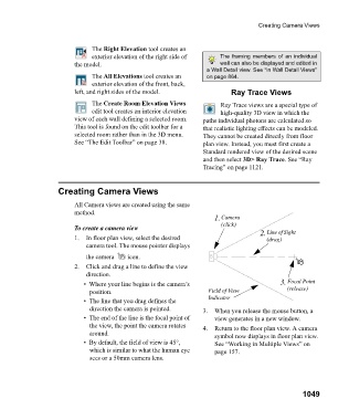
1. Camera
(click)
To create a camera view Line of Sight
1. In floor plan view, select the desired 2. (drag)
camera tool. The mouse pointer displays
the camera icon.
2. Click and drag a line to define the view
direction.
• Where your line begins is the camera’s 3. Focal Point
position. Field of View (release)
Indicator
• The line that you drag defines the
direction the camera is pointed. 3. When you release the mouse button, a
• The end of the line is the focal point of view generates in a new window.
the view, the point the camera rotates 4. Return to the floor plan view. A camera
around.
symbol now displays in floor plan view.
• By default, the field of view is 45°, See “Working in Multiple Views” on
which is similar to what the human eye page 157.
sees or a 50mm camera lens.
1049