
Page 1053 - Chief Architect Reference Manual
P. 1053
Cross Section/Elevation Views
The Wall Elevation tool creates an
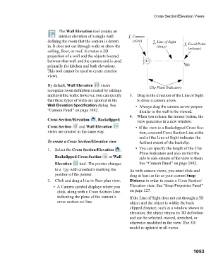
interior elevation of a single wall 1. Camera
defining the room that the camera is drawn (click) 2. Line of Sight
in. It does not cut through walls or show the (drag) 3. Focal Point
(release)
ceiling, floor, or roof. It creates a 2D
projection of a wall and the objects located
between that wall and the camera and is used
primarily for kitchen and bath elevations.
This tool cannot be used to create exterior
views.
By default, Wall Elevation v i e w s Clip Plane Indicators
recognize room definition created by railings
and invisible walls; however, you can specify 3. Drag in the direction of the Line of Sight
that these types of walls are ignored in the to draw a camera arrow.
Wall Elevation Specification dialog. See • Always drag the camera arrow perpen-
“Camera Panel” on page 1082. dicular to the wall to be viewed.
4. When you release the mouse button, the
Cross Section/Elevation , Backclipped
view generates in a new window.
Cross Section a n d Wall Elevation • If the view is a Backclipped Cross Sec-
views are created in the same way. tion, a second Cross Section Line at the
end of the Line of Sight indicates the
To create a Cross Section/Elevation view furthest extent of the backclip.
1. Select the Cross Section/Elevation , • You can specify the length of the Clip
Plane Indicators and also restrict the
Backclipped Cross Section or Wall side to side extents of the view to them.
Elevation tool. The pointer changes See “Camera Panel” on page 1082.
to a with crosshairs marking the As with camera views, you must click and
position of the pointer. drag at least as far as your current Snap
2. Click and drag a line in floor plan view. Distance in order to create a Cross Section/
• A Camera symbol displays where you Elevation view. See “Snap Properties Panel”
click, along with a Cross Section Line on page 127.
indicating the plane of the camera’s If the Line of Sight does not cut through a 3D
cross section cut line. object and the object is within the back
clipped distance, such as a window shown in
elevation, the object retains its 3D definition
and can be selected, moved, stretched, or
otherwise modified in the view. The 3D
model is updated in all views.
1053