
Page 1057 - Chief Architect Reference Manual
P. 1057
Displaying 3D Views
Auto Detail as Insulation is not available if
can generate an Insulation CAD box.
See “Insulation” on page 318. the selected layer has a “Gap” Material Type
assigned to it.
When Auto Detail as Insulation is checked
See “Wall Type Definitions Dialog” on page
for a layer, Auto Detail will produce an 386 and “Material Layers Definition
Insulation box instead of a polyline with a fill Dialogs” on page 1001.
style - even if a fill style is also specified.
Displaying 3D Views
A variety of tools and settings allow you to To show framing in a cross section/elevation
control the appearance of your 3D views. view, framing must first be built using the
There are also numerous ways to adjust the Build Framing dialog and the appropriate
position, focal point and field of view of a framing layers must be turned on in the
3D view. See “Editing 3D Views” on page Section View layer set. See “Framing” on
1066. page 835.
The name of the current plan file and the type
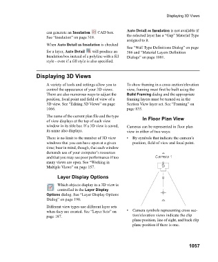
of view displays at the top of each view In Floor Plan View
window in its title bar. If a 3D view is saved, Cameras can be represented in floor plan
its name also displays. view in either of two ways:
There is no limit to the number of 3D view • By symbols that indicate the camera’s
windows that you can have open at a given position, field of view and focal point.
time; bear in mind, though, that each window
demands use of your computer’s resources
and that you may see poor performance if too
many views are open. See “Working in
Multiple Views” on page 157.
Layer Display Options
Which objects display in a 3D view is
controlled in the Layer Display
Options dialog. See “Layer Display Options
Dialog” on page 190.
Different view types use different layer sets
when they are created. See “Layer Sets” on • Camera symbols representing cross sec-
page 187. tion/elevation views indicate the clip
plane position, line of sight, and back clip
plane position if there is one.
1057