
Page 1055 - Chief Architect Reference Manual
P. 1055
Auto Detail
Labels for cabinets and other objects
can display in cross section/elevation
views. See “Displaying Labels” on page 682.
A selection of Auto Elevation Dimension
tools automatically generate dimension sets
and story poles in cross section/elevation
views. See “The Automatic Dimension
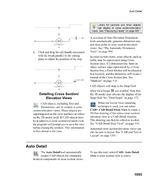
4. Click and drag the edit handle associated Tools” on page 469.
with the break parallel to the cutting In cross section views, some objects, such as
plane to adjust the position of the step. walls, may be represented using Cross
Section lines. If a dimension line finds an
object surface edge represented by a Cross
Section line, a Point Marker will be placed at
that location, and the dimension will locate it
instead of the Cross Section line. See
“Markers” on page 516.
CAD objects will snap to the Snap Grid
when Grid Snaps are enabled. Note that
Detailing Cross Section/ the 3D model may obscure the display of the
Elevation Views Snap Grid. See “Grid Snaps” on page 172.
CAD objects, including Text and When the Vector View rendering
Dimensions, can be created in cross technique is used, you can select
section/elevation views. These objects are CAD> CAD Detail From View to create a
superimposed on the view and have no effect 2D line drawing of the active cross section/
on the 3D model itself. If CAD objects have elevation view in a CAD Detail window.
been added to a cross section/elevation view, This drawing can then be edited as needed.
the program will prompt you to save the view See “CAD Detail from View” on page 334.
before closing the window. This information Annotated cross section/elevation views can
is then stored in the view. also be sent to layout. See “CAD and Text in
Layout” on page 1291.
Auto Detail
The Auto Detail tool automatically To use this tool, select CAD> Auto Detail
creates CAD objects for commonly while a cross section view is active.
detailed components of cross section views.
1055