
Page 1202 - Chief Architect Reference Manual
P. 1202
Terrain Perimeter
building site. For more information, see “Site
Window . See “Zoom Tools” on page
160. Plans” on page 451 of the User’s Guide.
Another approach is to use the Plan
When created in a new, blank plan, a new
terrain perimeter will be 50’ x 100’. If you Footprint tool and other CAD Tools in a
create a terrain perimeter after you have CAD Detail. See “Plan Footprint” on page
drawn all or part of a 3D model, it may 335.
increase in size as needed to encompass
everything in floor plan view. Terrain Height vs Floor Height
Once created, the terrain perimeter can be Chief Architect always defines the default
resized and edited like other polyline-based height of Floor 1 at 0’-0”. This height value
objects. See “Editing Closed-Polyline Based is the constant by which the heights of
Objects” on page 231. structural elements in the program like walls,
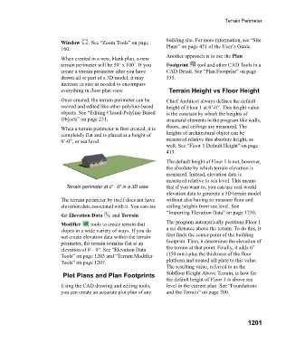
When a terrain perimeter is first created, it is floors, and ceilings are measured. The
completely flat and is placed at a height of heights of architectural object can be
0’-0”, or sea level. measured relative this absolute height, as
well. See “Floor 1 Default Height” on page
413.
The default height of Floor 1 is not, however,
the absolute by which terrain elevation is
measured. Instead, elevation data is
measured relative to sea level. This means
Terrain perimeter at 0' - 0" in a 3D view that if you want to, you can use real-world
elevation data to generate a 3D terrain model
The terrain perimeter by itself does not have without also having to measure floor and
elevation data associated with it. You can use ceiling heights from sea level. See
“Importing Elevation Data” on page 1230.
the Elevation Data and Terrain
Modifier tools to create terrain that The program automatically positions Floor 1
slopes in a wide variety of ways. If you do a set distance above the terrain. To do this, it
not create elevation data within the terrain first finds the center point of the building
perimeter, the terrain remains flat at an footprint. Then, it determines the elevation of
elevation of 0' - 0". See “Elevation Data the terrain at that point. Finally, it adds 6”
Tools” on page 1203 and “Terrain Modifier (150 mm) plus the thickness of the floor
Tools” on page 1207. platform and treated sill plate to this value.
The resulting value, referred to as the
Plot Plans and Plan Footprints Subfloor Height Above Terrain, is how far
the default height of Floor 1 is above sea
Using the CAD drawing and editing tools, level in the current plan. See “Foundations
you can create an accurate plot plan of any and the Terrain” on page 700.
1201