
Page 33 - Airstream™ Series Dryer
P. 33
AIRSTREAM™ SERIES DRYER
Installation
Utilities Electrical
Standard Airstream™ Dryer ONLY
If your dryer is equipped with the optional solenoid to raise the Top Nozzle on demand, run control
wiring from your “Car Wash Controller Relay” to the solenoid valve mounted on crossbeam of the head
frame assembly. This control wiring MUST provide the voltage to the valve.
Pro Airstream™ Dryer ONLY
If you wish to raise the Top Nozzle on demand, run control wiring (2 wires) from the Dryer Control
Panel to your Car Wash Controller Relay. This relay MUST provide a dry contact, as the control voltage
is provided by the Dryer Control Panel.
CAUTION
Failure to provide a dry contact will result in immediate damage to the computer inside of the
dryer control panel. Damage resulting from failure to provide a dry contact is easily identified,
and is not covered in the warranty.
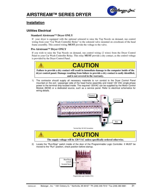
1) The contractor should supply all necessary materials to run conduit to the Dryer Control Panel
mounted on the exit / passenger side of the head frame assembly and install 120 VAC single-phase
power to the terminal strip located inside. The required 120VAC can be supplied by the Motor Control
Module (MCM) or a dedicated source, such as a service panel. Refer to electrical schematics for
wiring details.
Neutral
Ground
Hot
Terminal Strip 120 VAC Connections
CAUTION
The supply voltage will be 120 VAC unless specifically ordered otherwise.
2) Locate the “Run/Stop” switch inside of the door of the Programmable Logic Controller. It MUST be
moved to the “Run” position, check position before startup.
Run/Stop
switch
located here
Programmable Logic Controller (PLC)
1MANUL021 Belanger , Inc. * 1001 Doheny Ct. * Northville, MI 48167 * Ph (248) 349-7010 * Fax (248) 380-9681 31