
Page 42 - Kondor® KL 1 - E-1063 Programming and Operation Manual
P. 42
®
KL1: 1063 PROGRAMMING AND OPERATION
Chapter 5 Techniques in Programming
Configuring the Multifunctional Sonar Unit
This Multifunction Sonar has multiple modes for utilizing the same sonar unit on various pieces of Belanger® equipment. The modes are
switched by holding a magnet up to the designated location of the sonar unit until it switches into the corresponding mode. The LED on
the sonar will flash a pulse pattern count that corresponds to the MODE number that it’s in.
The modes are as follows:
MODE 1: Vector® Length (frequency)
MODE 2: Vector® Width (frequency)
MODE 3: FreeStyler® (frequency)
MODE 4: Saber® (frequency)
MODE 5: Vector® Length (digital)
MODE 6: Vector® Width (digital)
MODE 7: Kondor® Width (frequency)
The frequency modes output changes in frequency corresponding to the measured distance from the face of the sonar. Digital modes
turn on the output when the floor is detected.
Changing the Parameters
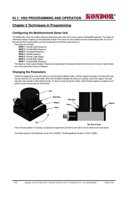
Holding the magnet to the sonar will cause it to cycle through the different modes. Hold the magnet horizontally on the top of the wide
ring and under the LED, as shown below. When the LED pattern indicates the mode you’re seeking, remove the magnet. The sonar
may take a few seconds to start switching modes. If it does not cycle through the modes, confirm that the magnet is up against round
portion of sonar near the base as shown below.
LED
Wide Ring
Wide Ring
Magnet Magnet
Base
Base
Side View of Sonar
If the LED pulse pattern is not cycling, try rotating the magnet back and forth to each side of LED as shown by the arrow above.
The model number for the Multifunction Sonar Unit is IR2005R. The Belanger® part number is 1ELECT-SN950.
5-2 Belanger, Inc.® * PO BOX 5470 * Northville, MI 48167-5470 * Ph (248) 349-7010 * Fax (248) 380-9681 1MANUL126