
Page 26 - Airblade® Dryer - Mix and Match
P. 26
AIRBLADE® DRYER Mix and Match
Installation
2-Nozzle Frame Assembly: Floor Mounted
Note: Drip space is the distance between the last Rinse Arch and the Dryer. Typically, the larger
the drip space, the better the Dryer can perform.
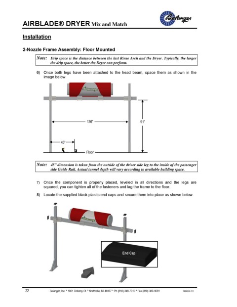
6) Once both legs have been attached to the head beam, space them as shown in the
image below.
136” 91”
45”
Floor
Note: 45” dimension is taken from the outside of the driver side leg to the inside of the passenger
side Guide Rail. Actual tunnel depth will vary according to available building space.
7) Once the component is properly placed, leveled in all directions and the legs are
squared, you can tighten all of the fasteners and lag the frame to the floor.
8) Locate the supplied black plastic end caps and secure them into place as shown below.
End Cap
22 Belanger, Inc. * 1001 Doheny Ct. * Northville, MI 48167 * Ph (810) 349-7010 * Fax (810) 380-9681 1MANUL011