
Page 18 - Tunnel Support Components
P. 18
TUNNEL SUPPORT COMPONENTS
Installation
10HP Hydraulic Unit
Fluid Cap
When doing maintenance, be sure fluid cap is securely tightened so not to allow debris to get inside of
the tank.
CAUTION
If the reservoir needs to be refilled, be sure to use the same type used during initial startup.
NEVER mix the two fluid types together!
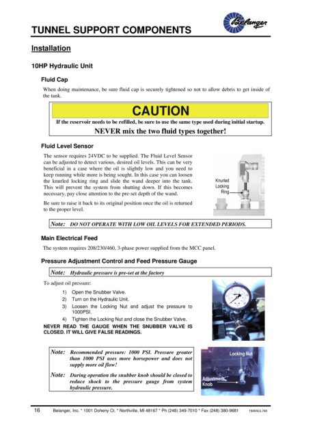
Fluid Level Sensor
The sensor requires 24VDC to be supplied. The Fluid Level Sensor
can be adjusted to detect various, desired oil levels. This can be very
beneficial in a case where the oil is slightly low and you need to
keep running while more is being sought. In this case you can loosen
the knurled locking ring and slide the wand deeper into the tank. Knurled
This will prevent the system from shutting down. If this becomes Locking
necessary, pay close attention to the pre-set depth of the wand. Ring
Be sure to raise it back to its original position once the oil is returned
to the proper level.
Note: DO NOT OPERATE WITH LOW OIL LEVELS FOR EXTENDED PERIODS.
Main Electrical Feed
The system requires 208/230/460, 3-phase power supplied from the MCC panel.
Pressure Adjustment Control and Feed Pressure Gauge
Note: Hydraulic pressure is pre-set at the factory
To adjust oil pressure:
1) Open the Snubber Valve.
2) Turn on the Hydraulic Unit.
3) Loosen the Locking Nut and adjust the pressure to
1000PSI.
4) Tighten the Locking Nut and close the Snubber Valve.
NEVER READ THE GAUGE WHEN THE SNUBBER VALVE IS
CLOSED. IT WILL GIVE FALSE READINGS.
Note: Recommended pressure: 1000 PSI. Pressure greater Locking Nut
than 1000 PSI uses more horsepower and does not
supply more oil flow!
Note: During operation the snubber knob should be closed to
reduce shock to the pressure gauge from system Adjustment
Knob
hydraulic pressure.
16 Belanger, Inc. * 1001 Doheny Ct. * Northville, MI 48167 * Ph (248) 349-7010 * Fax (248) 380-9681 1MANUL760