
Page 22 - Tunnel Support Components
P. 22
TUNNEL SUPPORT COMPONENTS
Installation
20HP Hydraulic Unit
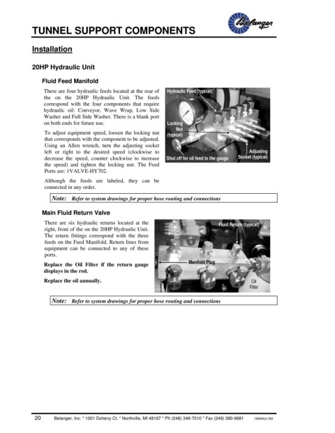
Fluid Feed Manifold
There are four hydraulic feeds located at the rear of Hydraulic Feed (typical)
the on the 20HP Hydraulic Unit. The feeds
correspond with the four components that require
hydraulic oil: Conveyor, Wave Wrap, Low Side
Washer and Full Side Washer. There is a blank port
on both ends for future use. Locking
Nut
To adjust equipment speed, loosen the locking nut (typical)
that corresponds with the component to be adjusted.
Using an Allen wrench, turn the adjusting socket
left or right to the desired speed (clockwise to Adjusting
decrease the speed, counter clockwise to increase Shut off for oil feed to the gauge Socket (typical)
the speed) and tighten the locking nut. The Feed
Ports are: 1VALVE-HY702.
Although the feeds are labeled, they can be
connected in any order.
Note: Refer to system drawings for proper hose routing and connections
Main Fluid Return Valve
There are six hydraulic returns located at the Fluid Return (typical)
right, front of the on the 20HP Hydraulic Unit.
The return fittings correspond with the three
feeds on the Feed Manifold. Return lines from
equipment can be connected to any of these
ports.
Replace the Oil Filter if the return gauge Manifold Plug
displays in the red.
Replace the oil annually. Oil
Filter
Note: Refer to system drawings for proper hose routing and connections
20 Belanger, Inc. * 1001 Doheny Ct. * Northville, MI 48167 * Ph (248) 349-7010 * Fax (248) 380-9681 1MANUL760