
Page 14 - Triple Foaming Sticks
P. 14
TRIPLE FOAMING STICKS
Installation
Utilities
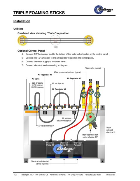
Overhead view showing “Tee’s” in position
Tees
Optional Control Panel
4) Connect 1/2” fresh water feed to the bottom of the water valve located on the control panel.
5) Connect the 1/2” air supply to the air regulator located on the control panel,
6) Connect the water supply to the water valve.
7) Connect electrical feeds according to diagram.
Water valve (typical)
Water pressure adjustment (typical)
Air Regulator #1
Air Valve Air Regulator #3
Main air supply Air out (typical)
90-PSI minimum
120-PSI maximum
Air Regulator #2
Air pressure
adjustment (typical)
Air valve electrical IN
Water
solenoid
electrical IN
Main water feed from
a shut-off valve, 1/2”
Chemical Chemical Chemical
Pump #1 Pump #2 Pump #3
Chemical feeds located
at rear of pumps
12 Belanger, Inc. * 1001 Doheny Ct. * Northville, MI 48167 * Ph (248) 349-7010 * Fax (248) 380-9681 1MANUAL753