
Page 50 - DryLite® Dryers
P. 50
®
DRYLITE DRYER
Chapter 3: Installation of DryLite® with Air Cannons™
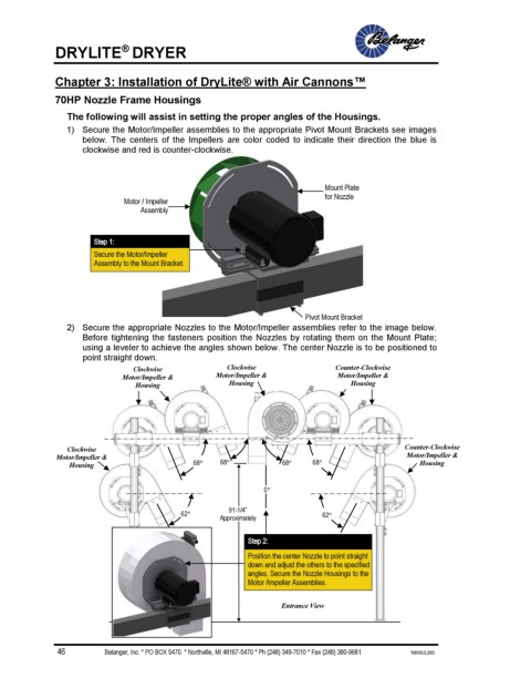
70HP Nozzle Frame Housings
The following will assist in setting the proper angles of the Housings.
1) Secure the Motor/Impeller assemblies to the appropriate Pivot Mount Brackets see images
below. The centers of the Impellers are color coded to indicate their direction the blue is
clockwise and red is counter-clockwise.
Mount Plate
for Nozzle
Motor / Impeller
Assembly
Step 1:
Secure the Motor/Impeller
Assembly to the Mount Bracket.
Pivot Mount Bracket
2) Secure the appropriate Nozzles to the Motor/Impeller assemblies refer to the image below.
Before tightening the fasteners position the Nozzles by rotating them on the Mount Plate;
using a leveler to achieve the angles shown below. The center Nozzle is to be positioned to
point straight down.
Clockwise Clockwise Counter-Clockwise
Motor/Impeller & Motor/Impeller & Motor/Impeller &
Housing Housing Housing
Clockwise Counter-Clockwise
Motor/Impeller & Motor/Impeller &
Housing 68 68 68 68 Housing
0
91-1/4”
62 62
Approximately
Step 2:
Position the center Nozzle to point straight
down and adjust the others to the specified
angles. Secure the Nozzle Housings to the
Motor /Impeller Assemblies.
Entrance View
46 Belanger, Inc. * PO BOX 5470. * Northville, MI 48167-5470 * Ph (248) 349-7010 * Fax (248) 380-9681 1MANUL960