Page 55 - DryLite® Dryers
P. 55

®
                       DRYLITE  DRYER

                       Chapter 4: Installation of DryLite® - Air Cannons™ & SideKicks®

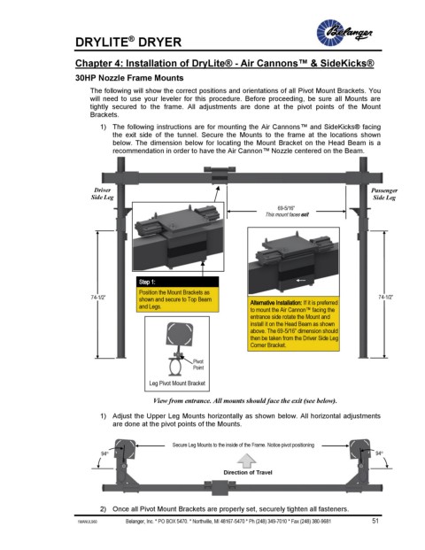
                       30HP Nozzle Frame Mounts

                           The following will show the correct positions and orientations of all Pivot Mount Brackets. You
                           will  need  to  use  your  leveler  for  this  procedure.  Before  proceeding,  be  sure  all  Mounts  are
                           tightly  secured  to  the  frame.  All  adjustments  are  done  at  the  pivot  points  of  the  Mount
                           Brackets.
                              1)  The following instructions are for mounting the Air Cannons™ and SideKicks® facing
                                 the  exit  side  of  the  tunnel.  Secure  the  Mounts  to  the  frame  at  the  locations  shown
                                 below. The  dimension below for locating  the Mount  Bracket on the  Head  Beam is a
                                 recommendation in order to have the Air Cannon™ Nozzle centered on the Beam.


                            Driver                                                                          Passenger
                           Side Leg                                                                          Side Leg
                                                                                 69-5/16”
                                                                             This mount faces exit


                                         Step 1:
                                         Position the Mount Brackets as
                           74-1/2”       shown and secure to Top Beam                                         74-1/2”
                                         and Legs.                       Alternative Installation: If it is preferred
                                                                         to mount the Air Cannon™ facing the
                                                                         entrance side rotate the Mount and
                                                                         install it on the Head Beam as shown
                                                                         above. The 69-5/16” dimension should
                                                                         then be taken from the Driver Side Leg
                                                                         Corner Bracket.

                                                         Pivot
                                                         Point

                                            Leg Pivot Mount Bracket
                                             View from entrance. All mounts should face the exit (see below).

                              1)  Adjust the Upper Leg Mounts horizontally as shown below. All horizontal adjustments
                                 are done at the pivot points of the Mounts.


                                                   Secure Leg Mounts to the inside of the Frame. Notice pivot positioning
                              94                                                                            94

                                                                 Direction of Travel


                              2)  Once all Pivot Mount Brackets are properly set, securely tighten all fasteners.
                       1MANUL960                         Belanger, Inc. * PO BOX 5470. * Northville, MI 48167-5470 * Ph (248) 349-7010 * Fax (248) 380-9681                          51
   50   51   52   53   54   55   56   57   58   59   60