
Page 18 - Gyro Wrap™
P. 18
™
GYRO WRAP
Installation
Tunnel Placement
When placing a piece of equipment, tunnel depth will vary from site to site. Be sure to allow an
adequate operating envelope as shown on the previous pages for Right-Hand and Left-Hand Drive
systems.
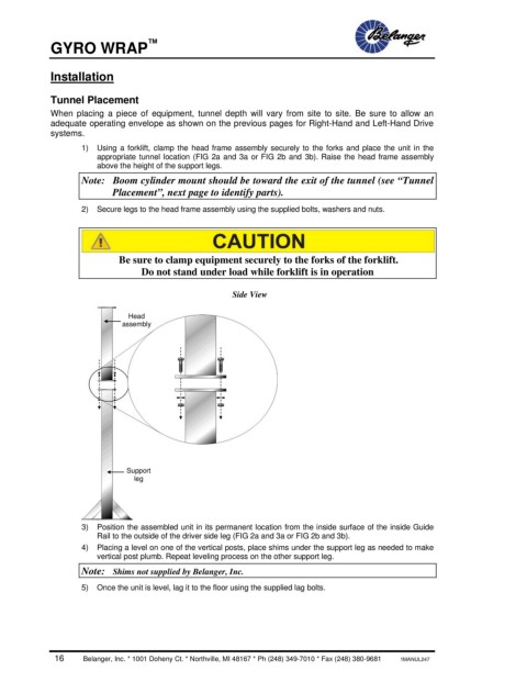
1) Using a forklift, clamp the head frame assembly securely to the forks and place the unit in the
appropriate tunnel location (FIG 2a and 3a or FIG 2b and 3b). Raise the head frame assembly
above the height of the support legs.
Note: Boom cylinder mount should be toward the exit of the tunnel (see “Tunnel
Placement”, next page to identify parts).
2) Secure legs to the head frame assembly using the supplied bolts, washers and nuts.
Be sure to clamp equipment securely to the forks of the forklift.
Do not stand under load while forklift is in operation
Side View
Head
assembly
Support
leg
3) Position the assembled unit in its permanent location from the inside surface of the inside Guide
Rail to the outside of the driver side leg (FIG 2a and 3a or FIG 2b and 3b).
4) Placing a level on one of the vertical posts, place shims under the support leg as needed to make
vertical post plumb. Repeat leveling process on the other support leg.
Note: Shims not supplied by Belanger, Inc.
5) Once the unit is level, lag it to the floor using the supplied lag bolts.
16 Belanger, Inc. * 1001 Doheny Ct. * Northville, MI 48167 * Ph (248) 349-7010 * Fax (248) 380-9681 1MANUL247