
Page 23 - Top Wheel Mix & Match
P. 23
TOP WHEEL Mix and Match
Installation
Frame Assembly
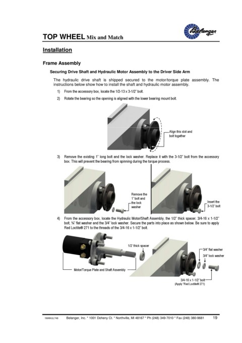
Securing Drive Shaft and Hydraulic Motor Assembly to the Driver Side Arm
The hydraulic drive shaft is shipped secured to the motor/torque plate assembly. The
instructions below show how to install the shaft and hydraulic motor assembly.
1) From the accessory box, locate the 1/2-13 x 3-1/2” bolt.
2) Rotate the bearing so the opening is aligned with the lower bearing mount bolt.
Align this slot and
bolt together
3) Remove the existing 1” long bolt and the lock washer. Replace it with the 3-1/2” bolt from the accessory
box. This will prevent the bearing from spinning during the torque process.
Remove the
1” bolt and
the lock Insert the
washer 3-1/2” bolt
4) From the accessory box, locate the Hydraulic Motor/Shaft Assembly, the 1/2” thick spacer, 3/4-16 x 1-1/2”
bolt, ¾” flat washer and the 3/4” lock washer. Secure the parts into place as shown below. Be sure to apply
Red Loctite® 271 to the threads of the 3/4-16 x 1-1/2” bolt.
1/2’ thick spacer
3/4” flat washer
3/4” lock washer
Motor/Torque Plate and Shaft Assembly
3/4-16 x 1-1/2” bolt
(Apply “Red Loctite® 271)
1MANUL749 Belanger, Inc. * 1001 Doheny Ct. * Northville, MI 48167 * Ph (248) 349-7010 * Fax (248) 380-9681 19