
Page 59 - AirBlade® Dryer Signature® Series
P. 59
AIRBLADE® DRYER Signature ® Series
Installation
AirBlade® Express 180, Frame Assembly
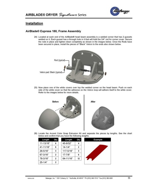
24) Located at each end of the AirBlade® head beam assembly is a welded corner that has 2 gussets
welded on it. Each gusset has a through hole in it that will hold the 3/4” rod for corner cover. Secure
the rods in place and tighten down completely as shown in the images below. Once the Rods have
been secured in place, install the pieces of “Black” Velcro to the ends also shown below.
Rod (typical)
Velcro pad: Black (typical)
25) Now place one of the white covers over top the welded corner on the head beam. Push on each
side of the white cover so that the adhesive on the Velcro loop will adhere itself to the white cover.
Refer to the images below for more details.
Before After
26) Locate the Accent Color Snap Extrusion Kit and separate the pieces by lengths. See the chart
below and confirm that you have the following lengths.
Length Qty Length Qty Example
11-13/16” 6 45-9/32” 4
41-11/16” 6 14-1/4” 2
29-5/16” 3 117-5/16” 3
67-3/16” 2 17-7/8” 6
78-3/16” 2 64-11/16” 12
25-1/4” 2
1MANUL009 Belanger, Inc. * 1001 Doheny Ct. * Northville, MI 48167 * Ph (810) 349-7010 * Fax (810) 380-9681 55