
Page 55 - AirBlade® Dryer Signature® Series
P. 55
AIRBLADE® DRYER Signature ® Series
Installation
AirBlade® Express 180, Frame Assembly
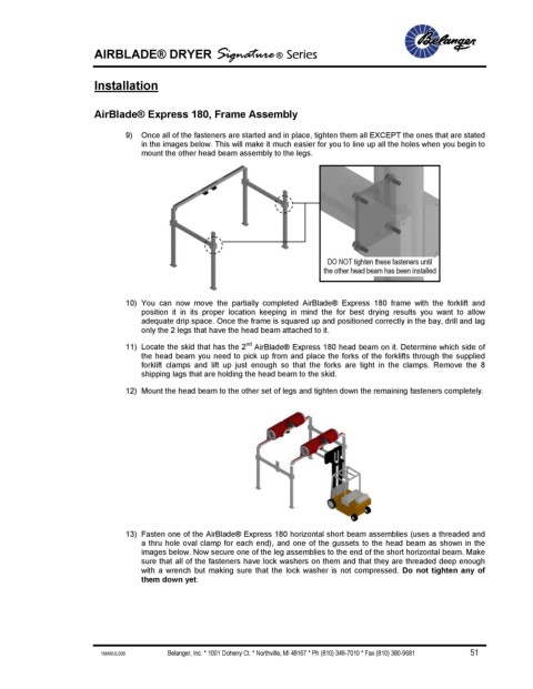
9) Once all of the fasteners are started and in place, tighten them all EXCEPT the ones that are stated
in the images below. This will make it much easier for you to line up all the holes when you begin to
mount the other head beam assembly to the legs.
DO NOT tighten these fasteners until
the other head beam has been installed
10) You can now move the partially completed AirBlade® Express 180 frame with the forklift and
position it in its proper location keeping in mind the for best drying results you want to allow
adequate drip space. Once the frame is squared up and positioned correctly in the bay, drill and lag
only the 2 legs that have the head beam attached to it.
nd
11) Locate the skid that has the 2 AirBlade® Express 180 head beam on it. Determine which side of
the head beam you need to pick up from and place the forks of the forklifts through the supplied
forklift clamps and lift up just enough so that the forks are tight in the clamps. Remove the 8
shipping lags that are holding the head beam to the skid.
12) Mount the head beam to the other set of legs and tighten down the remaining fasteners completely.
13) Fasten one of the AirBlade® Express 180 horizontal short beam assemblies (uses a threaded and
a thru hole oval clamp for each end), and one of the gussets to the head beam as shown in the
images below. Now secure one of the leg assemblies to the end of the short horizontal beam. Make
sure that all of the fasteners have lock washers on them and that they are threaded deep enough
with a wrench but making sure that the lock washer is not compressed. Do not tighten any of
them down yet.
1MANUL009 Belanger, Inc. * 1001 Doheny Ct. * Northville, MI 48167 * Ph (810) 349-7010 * Fax (810) 380-9681 51