
Page 12 - stanochny park
P. 12
METALWORKING EQUIPMENT AND TOOLS METALWORKING EQUIPMENT AND TOOLS
carried out by reducing and then turning off the previously known method of blowing with bias towards the knockout. to use a plate one, and the sand 6 is poured on a model
vacuum (as the conveyor belt leaves the zone of heated air, the heating time of the film is After filling the cavities with plates of such a conveyor 2, a film 7 from a roll 8 is
connection to the vacuum system), transferring reduced. And heating the paint reduces metal and cooling the casting can be made with cavities laid on a roll counter 9 with a
sand from the stony state to loose. the drying time, and this complex lining- sand and castings are removed and vacuum valves 22 (Fig. simultaneous molding of filling
In the invention [5], it was proposed not painting operation easily fits into the from the mold, sand is fed into 1h) by alternately connecting funnels 10. Usually, a frame
to carry cooling castings on the conveyor in continuous molding process. The degree the cooling - recycling system, these cavities to an external device is used to apply film
loose sandy medium, but to feed them into a of compaction of sand can be increased traditionally used for VFM. vacuum system 23 [7]. to Model 2. The description
closed inclined trench (as a continuation of the by applying vibration of the roll, or other For the manufacture of Conveyor plates can have [4] shows an example of a
conveyor), along the walls of which the castings in known methods. semi-continuous thick-walled hollow perforated sidewalls design 5 of a frame type with
sand move by sliding under their own weight and The sand layer is vaccumed through profiles, a rotary mechanism 24 and longitudinal partitions a rotating frame with double-
are in the trench until the temperature reaches, the mesh filters 15 (Fig. 1f), mounted can be used (Fig. 1g) in 25, the latter, it is advisable to sided film suction cups. With
at which prescribed the embossing of sand forms. in the tape 1 and having valves 16, the form of a frame 19 with mount on multi-strand molds. each rotation of 180º around
This significantly reduces the power conveyor. Let which are connected to the system 17 of a drive 20, on which two The mold is transported on an axis perpendicular to
us consider in more detail the design of foundry pipelines for vacuum tracking the moving rolls with models of various rollers 26. the direction of movement
conveyor systems. tape, after which the sand acquires the configurations are installed. To obtain castings in of the conveyor, the frame
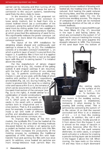
The layout of the VFM installation for strength inherent in VPM. The thickness When exposed to the sand of a continuous vacuum form, alternately spreads the film on
obtaining simple shaped and continuously cast of the sand layer from the bottom of one of the rolls, cavities are consisting of two half-molds, the model one after the other.
castings is shown in Fig. 1a [3]. The installation formed, and when the rolls the following installation was The lower half-mold is
consists of a movable conveyor-crystallizer 1, on are removed from the sand developed, the scheme of assembled from segments
which a uniform layer of sand 2 is poured from the and the horizontal position of which is shown in Fig. 2a [4]. 11. For pouring, use a bucket
hopper 3. A synthetic film 5 from roll 6 is applied the frame 19, a partition 21 is The installation consists of a 12. After pouring, the mold is
to the roll 4, and then the film is laid on the sand obtained between the cavities conveyor 1 of model plates smoothly placed in a closed
layer with this roll. A casting bucket 7 is installed [6]. In this case, instead of a with models 2, onto which a inclined chute 13, where the
above the mold. conveyor belt for a movable synthetic film 3 is laid from a casting is cooled and fed to
For the manufacture of simple shaped mold, it is more convenient roll 4 using a device 5. Then conveyor 14, and the sand
castings on roll 4 (Fig. 1b), models of the gating
system 8 and shaped castings 9 are mounted,
with the help of which cavities 10 are obtained
(Fig. 1a). To perform continuous profiles, ring
models 11 and 12 are used, with the help of which
cavities with profiles 13 and 14, respectively,
are molded (Fig. 1d, 1e). During molding, the
model is pressed into the sand by a rotating
roller and leaves a film 5 on it, the remains of the casting cavity
which can be wound into a roll at the end of to the surface of the
the sand-lined section of the conveyor (see tape is 0.05 ... 0.10
Fig. 1a to the right). A model similar to a m. To facilitate the
combination of model constructions indentation efforts of
(Fig. 1b, 1d) can be mounted on the models in the molding section,
roll 4, which gives an imprint (a minimum vacuum is maintained,
cavity in the sand) with a variable increasing it when moving to the
surface both in longitudinal and in pouring and cooling areas. This is
cross section. That is, it is possible to achieved by connecting the system 17
pour, for example, in semi-continuous to the valves 16 so that the nearest
mode a rail with teeth of different connected belt filter is at a distance
profiles and simultaneously with rows of 0.5 ... 1.0 m from the molding
both along and across conveyor, etc. position. In addition, the roll 4 with
To improve the lining of the film with models forms sand, mostly poured on
models, the synthetic film 5 can be heated at the it from above from the hopper 3, and
time of lining (in this and other forming methods is almost on the verge of vacuum in
discussed below) by airless or air spraying such the sand, however, after the film is
a coolant as heated non-stick paint onto this film laid with the roll, the sand remains
[8]. The latter increases the productivity of the stationary. In some cases, a compact
molding process by combining the traditional sand cultivator or a device for creating
operations of VFM: heating the film with heat- a pseudo-boiling layer can be installed
transfer fluid and painting the film with non-stick in the hopper 3 above the roll. When
paint. In addition, since heated ink particles are moving, the tape rests on the rollers Fig. 2. Installation of VFM for the production of castings in the sand
more energy-intensive heat carriers than the 18 and may have a slight downward a form of two half-forms obtained continuously.
12 Stanochniy park Stanochniy park 13