
Page 15 - stanochny park
P. 15
METALWORKING EQUIPMENT AND TOOLS METALWORKING EQUIPMENT AND TOOLS
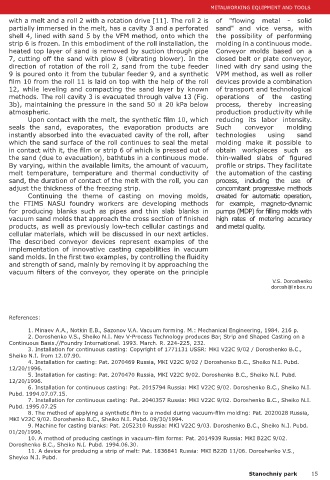
is poured into a receiving with a melt and a roll 2 with a rotation drive [11]. The roll 2 is of "flowing metal - solid
hopper 15 connected to the partially immersed in the melt, has a cavity 3 and a perforated sand" and vice versa, with
sand cooling and cleaning line. shell 4, lined with sand 5 by the VFM method, onto which the the possibility of performing
The FTIMS NASU uses high- strip 6 is frozen. In this embodiment of the roll installation, the molding in a continuous mode.
performance continuous sand heated top layer of sand is removed by suction through pipe Conveyor molds based on a
coolers in a pseudo-boiling 7, cutting off the sand with plow 8 (vibrating blower). In the closed belt or plate conveyor,
layer, which are built into direction of rotation of the roll 2, sand from the tube feeder lined with dry sand using the
automated sand conveying 9 is poured onto it from the tubular feeder 9, and a synthetic VPM method, as well as roller
lines from the knockout position film 10 from the roll 11 is laid on top with the help of the roll devices provide a combination
to the molding position. Since 12, while leveling and compacting the sand layer by known of transport and technological
dry sand (unlike traditional methods. The roll cavity 3 is evacuated through valve 13 (Fig. operations of the casting
molding sand mixtures) does 3b), maintaining the pressure in the sand 50 ± 20 kPa below process, thereby increasing
not lose flowability at low atmospheric. production productivity while
temperatures, such lines are Upon contact with the melt, the synthetic film 10, which reducing its labor intensity.
usually placed outside the seals the sand, evaporates, the evaporation products are Such conveyor molding
foundry, near its outer wall. instantly absorbed into the evacuated cavity of the roll, after technologies using sand
The lower half of the which the sand surface of the roll continues to seal the metal molding make it possible to
half-mold from segments in contact with it, the film or strip 6 of which is pressed out of obtain workpieces such as
11 is molded similarly to the In order to ensure that the side walls of adjacent segments 11 the sand (due to evacuation), bathtubs in a continuous mode. thin-walled slabs of figured
upper half-mold, with the only are joined without a gap during assembly, the model plate is By varying, within the available limits, the amount of vacuum, profile or strips. They facilitate
difference in this embodiment rotated by the specified angle α during molding compared to its melt temperature, temperature and thermal conductivity of the automation of the casting
of the design: on the model location at the time the model was pulled from the mold. sand, the duration of contact of the melt with the roll, you can process, including the use of
plate with model 16, a partition As shown in cross section (Fig. 2b), the mold has adjust the thickness of the freezing strip. concomitant progressive methods
17 is installed equal to the longitudinal sidewalls with vacuum valves 18 and perforated Continuing the theme of casting on moving molds, created for automatic operation,
height of the half-mold and walls 19 for sand vaccuuming when valves 18 are connected to the FTIMS NASU foundry workers are developing methods for example, magneto-dynamic
having an angle α at the apex. pipelines 20 of the vacuum tracking system for VFM lines. The for producing blanks such as pipes and thin slab blanks in pumps (MDP) for filling molds with
mold is moved on rollers 21. vacuum sand molds that approach the cross section of finished high rates of metering accuracy
Since there are no transverse partitions on the conveyor, products, as well as previously low-tech cellular castings and and metal quality.
using the appropriate models in this installation, cavity formation cellular materials, which will be discussed in our next articles.
is possible to obtain long castings in semi-continuous mode. The described conveyor devices represent examples of the
It should be noted that upon reaching the counterattack implementation of innovative casting capabilities in vacuum
of the form of strips, profits, when the form is filled with metal, sand molds. In the first two examples, by controlling the fluidity
the film burns around them. The depressurized surface of the and strength of sand, mainly by removing it by approaching the
sand mold leads to air suction through it and a significant vacuum filters of the conveyor, they operate on the principle
decrease in the degree of rarefaction in the upper part of the
V.S. Doroshenko
mold, which requires an increase in the intensive operation dorosh@inbox.ru
of the pumps to avoid premature softening of the mold. This
question is especially relevant for the installation shown in Fig.
1, during the operation of which extensive open metal surfaces
are possible. For individual molds in areas of manual molding, References:
in such cases, immediately after pouring, the end face of
the spike or profit is covered with sand, which prevents the 1. Minaev A.A., Notkin E.B., Sazonov V.A. Vacuum forming. M.: Mechanical Engineering, 1984. 216 p.
destruction of the nearby film. In the invention [10], sealing 2. Doroshenko V.S., Sheiko N.I. Nev V-Process Technology produces Bar, Strip and Shaped Casting on a
and «warming» of the exposed metal surfaces and parts of Continuous Basis.//Foundry International. 1993. March. R. 224-225, 232.
3. Installation for continuous casting: Copyright of 1771131 USSR: MKI V22C 9/02 / Doroshenko B.C.,
the mold surface around them are performed by covering with Sheiko N.I. from 12.07.90.
synthetic film bags filled with molding sand. During continuous 4. Installation for casting: Pat. 2070469 Russia, MKI V22C 9/02 / Doroshenko B.C., Sheiko N.I. Pubd.
casting on a moving conveyor, open metal surfaces and nearby 12/20/1996.
mold surfaces are covered with a continuously manufactured 5. Installation for casting: Pat. 2070470 Russia, MKI V22C 9/02. Doroshenko B.C., Sheiko N.I. Pubd.
sand bag, which is lined with a sand layer on the surface of 12/20/1996.
6. Installation for continuous casting: Pat. 2015794 Russia: MKI V22C 9/02. Doroshenko B.C., Sheiko N.I.
the flooded mold, it can be considered an analogue of the non- Pubd. 1994.07.07.15.
flammable sand-film non-vacuum form. This coating is much 7. Installation for continuous casting: Pat. 2040357 Russia: MKI V22C 9/02. Doroshenko B.C., Sheiko N.I.
more effective for sealing the mold than a simple dusting with Pubd. 1995.07.25
sand. The lower film of the bag in contact with metal burns out, 8. The method of applying a synthetic film to a model during vacuum-film molding: Pat. 2020028 Russia,
and the upper film of the lying bag serves as a reliable sealant. MKI V22C 9/02. Doroshenko B.C., Sheiko N.I. Pubd. 09/30/1994.
9. Machine for casting blanks: Pat. 2052310 Russia: MKI V22C 9/03. Doroshenko B.C., Sheiko N.I. Pubd.
An option is also provided for laying these sandbags on a mold 01/20/1996.
before pouring metal [10]. 10. A method of producing castings in vacuum-film forms: Pat. 2014939 Russia: MKI B22C 9/02.
For continuous production of a strip from a melt, a roll Doroshenko B.C., Sheiko N.I. Pubd. 1994.06.30.
Fig. 3. Device for continuous strip from
the melt. device has been developed (Fig. 3a), consisting of a bath 1 11. A device for producing a strip of melt: Pat. 1836841 Russia: MKI B22D 11/06. Doroshenko V.S.,
Sheyko N.I. Pubd.
14 Stanochniy park Stanochniy park 15