
Page 2190 - Foton Workshop Manual - Aumark (BJ1099)
P. 2190
62-138 DIAGNOSIS-POWER DOOR LOCK
Is the result normal?
Yes>To step 4.
No >Repair the open circuit between the No.6 pin of the connector G07 on the right front
door lock motor and the No.E16 pin of the connector C58 on the body controller.
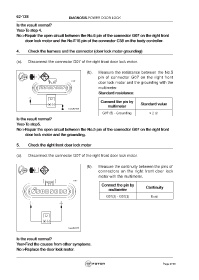
4. Check the harness and the connector (door lock motor-grounding)
(a). Disconnect the connector G07 of the right front door lock motor.
(b). Measure the resistance between the No.5
pin of connector G07 on the right front
door lock motor and the grounding with the
multimeter.
Standard resistance:
Connect the pin by Standard value
multimeter
G07 (5) - Grounding ≤ 2 Ω
Is the result normal?
Yes>To step5.
No >Repair the open circuit between the No.5 pin of the connector G07 on the right front
door lock motor and the grounding.
5. Check the right front door lock motor
(a). Disconnect the connector G07 of the right front door lock motor.
(b). Measure the continuity between the pins of
connectors on the right front door lock
motor with the multimeter.
Connect the pin by Continuity
multimeter
G07(2) - G07(3) Exist
Is the result normal?
Yes>Find the causes from other symptoms.
No >Replace the door lock motor.
Page 2190