
Page 2188 - Foton Workshop Manual - Aumark (BJ1099)
P. 2188
62-136 DIAGNOSIS-POWER DOOR LOCK
Diagnosis Procedure
• This Diagnosis Procedure takes the right front door as the example, and so does that of
other door locks.
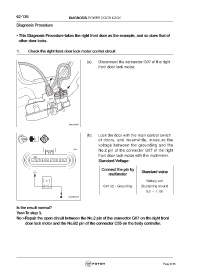
1. Check the right front door lock motor control circuit
(a). Disconnect the connector G07 of the right
front door lock motor.
fuwx62461
(b). Lock the door with the main control switch
of doors, and meanwhile, measure the
voltage between the grounding and the
No.2 pin of the connector G07 of the right
front door lock motor with the multimeter.
Standard Voltage:
Connect the pin by Standard value
multimeter
Battery volt
G07 (2) - Grounding (Sustaining around
0.3 ~ 1.1S)
Is the result normal?
Yes>To step 3.
No >Repair the open circuit between the No.2 pin of the connector G07 on the right front
door lock motor and the No.B2 pin of the connector C55 on the body controller.
Page 2188