
Page 2184 - Foton Workshop Manual - Aumark (BJ1099)
P. 2184
62-132 DIAGNOSIS-POWER DOOR LOCK
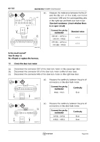
(e). Measure the resistance between the No.B1
and No.B2 pin of the body controller
connector C55 and the corresponding pins
of the right rear and front door lock motor.
Standard resistance: (check whether there
is an open circuit)
Connect the pin by Standard value
multimeter
C55 (B1) - G07(2) or
≤ 2 Ω
C55 (B1) -H05(2)
C55 (B2) - G07(3) or
≤ 2 Ω
C55 (B2) - H05(3)
Is the result normal?
Yes>To step 12.
No >Repair or replace the harness.
12. Check the door lock motor
(a). Disconnect the connector G07 of the door lock motor on the passenger door.
(b). Disconnect the connector I05 of the door lock motor on the left rear door.
(c). Disconnect the connector H05 of the door lock motor on the right rear door.
(d). Measure the continuity between the pins of
connectors on the door lock motor.
Connect the pin by Continuity
multimeter
I05(6) - I05(7) Exist
(e). Measure the continuity between the pins of
connectors on the door lock motor.
Connect the pin by Continuity
multimeter
G07(2) - G07(3) Exist
H05(2) - H05(3) Exist
Page 2184