Page 2183 - Foton Workshop Manual - Aumark (BJ1099)
P. 2183

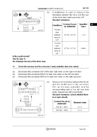
DIAGNOSIS-POWER DOOR LOCK                                62-131

                                                             (b).   A multimeter is used to measure the
                                                                   resistance between the No.5 and No.4 pin
                                                                   of the driver door locks connector J07.
                                                                   Standard resistance:

                                                                                 Connect the pin     Specified       62
                                                                    Conditions
                                                                                  by multimeter        value
                                                                      The lock
                                                                       state
                                                                     feedback     J07 (5) - J07 (4)    < 2 Ω
                                                                      switch is
                                                                       OFF

                                                                      The lock
                                                                       state
                                                                     feedback     J07 (5) - J07 (4)    Infinite
                                                                      switch is
                                                                        ON.
                 Is the result normal?
                 Yes>To step 11.
                 No >Replace the lock of the driver door.


                 11.    Check the harness and the connector ( body controller-door lock motor)


                 (a).   Disconnect the connector G07 of the door lock motor on the right front door.
                 (b).   Disconnect the connector I05 of the door lock motor on the left rear door.
                 (c).    Disconnect the connector H05 of the door lock motor on the right rear door.


                                                            (d).   Measure the resistance between the No.B1
                                                                   and  the  No.B2  pins of  the connector
                                                                   C57  on  the  body  controller  and  the
                                                                   corresponding pins of the left rear door
                                                                   motor respectively with a multimeter.
                                                                   Standard resistance: (check whether there
                                                                   is an open circuit)

                                                                     Connect the pin by       Standard value
                                                                          multimeter

                                                                        C55 (B1) - I05(7)          ≤ 2 Ω

                                                                        C55 (B2) - I05(6)          ≤ 2 Ω


                                                                                                     Page 2183
   2178   2179   2180   2181   2182   2183   2184   2185   2186   2187   2188