
Page 2189 - Foton Workshop Manual - Aumark (BJ1099)
P. 2189
DIAGNOSIS-POWER DOOR LOCK 62-137
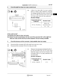
2. Check the right front door lock motor control circuit
(a). Unlock the door with the main control
switch of doors, and meanwhile,measure
the voltage between the grounding and the
No.3 pin of the connector G07 of the right 62
front door lock motor with the multimeter.
Standard Voltage:
Connect the pin by Standard value
multimeter
Battery volt
G07 (3) - Grounding (sustaining around
0.3 ~ 1.1s)
Is the result normal?
Yes>Replace the right front door lock motor.
No >Repair the open circuit between the No.3 pin of the connector G07 on the right front
door lock motor and the No.B1 pin of the connector C55 on the body controller.
3. Check the harness and the connector ( body controller-door lock motor)
(a). Disconnect the connector G07 of the right front door lock motor.
(b). Disconnect the connector C58 of the body controller.
(c). Measure the resistance between the No.6
pin of connector G07 on the right front
door lock motor and the No.E16 pin of the
connector C58 on the body controller with
the multimeter.
Standard resistance:
Connect the pin by Standard value
multimeter
G07(6) - C58(E16) ≤ 2 Ω
Page 2189