Page 2519 - Foton Workshop Manual - Sauvana
P. 2519

DIAGNOSIS-AUTOMATIC TRANSMISSION                            62-467

                 Check if the result is normal?
                 YES> To step 3.
                 NO> If connector TCU P01 Pin 14 has no battery voltage, repair the open circuit between
                         fuse F10 (10 A) and connector TCU P01 Pin 14.
                         If connector TCU P01 Pin 9 has no battery voltage, repair the open circuit between
                         fuse F19 (5 A) and connector TCU P01 Pin 9.                                                62


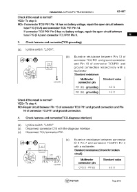
                 3.     Check harness and connector(TCU-grounding)


                 (a).   Ignition switch: "LOCK".


                                                            (b).   Examine resistance between Pin 13 of
                                                                   connector TCU P01 and ground connection
                    OFF
                                            Ω                      and Pin 16 of connector TCUP01 and
                                                                   ground connection respectively with a
                           P01
                           1
                         3
                          4   2                                    multimeter
                            5
                       10  8  6  7
                         11  9                                          Standard resistance:
                          12
                        15  13 14
                                                                         Multimeter          Standard value
                           16
                                                 fuwx62956             connection pin
                                                                     P01 (13) - grounding          ≤ 2 Ω
                                                                     P01 (16) - grounding          ≤ 2 Ω


                 Check if the result is normal?
                 YES> To step 4.
                 NO>Repair circuit between Pin 13 of connector TCU P01 and ground connection and Pin
                        16 of connector TCUP01 and ground connection.


                 4.     Check harness and connector(TCU-diagnose interface)


                 (a).   Ignition switch: "LOCK"
                 (b).   Disconnect connector C10 with the diagnose interface .
                 (c).   Disconnect TCU connector P01.


                                                            (c).   Examine resistance between connector
                                                                   C10 Pin 7 and connector TCUP01 Pin 3
                    OFF
                                      Ω                            with a multimeter.
                                                                        Standard resistance:(Check for broken
                           P01
                           1                                            circuit)
                         3                    C10
                          4   2
                            5
                       10  8  6  7
                         11  12  9        16 15 14 13  12  11 10  9      Multimeter          Standard value
                        15  13 14         8  7  6 5  4 3 2  1
                                                                       connection pin
                           16
                                                 fuwx62957
                                                                       C10 (7) - P01(3)            ≤ 2 Ω


                                                                                                     Page 2519
   2514   2515   2516   2517   2518   2519   2520   2521   2522   2523   2524